

NFAF135-S50
Description
Description
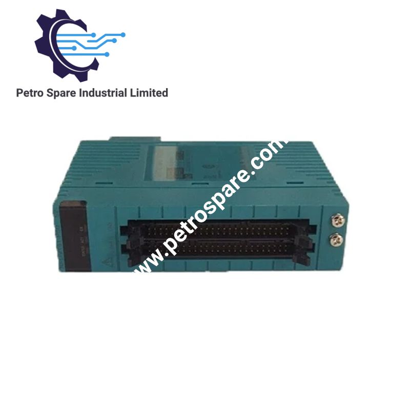
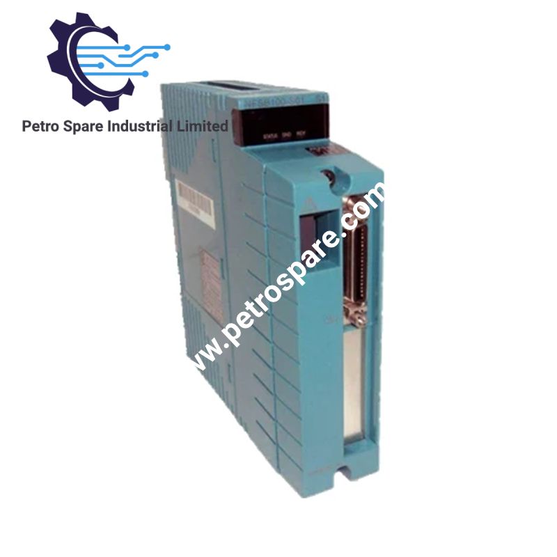
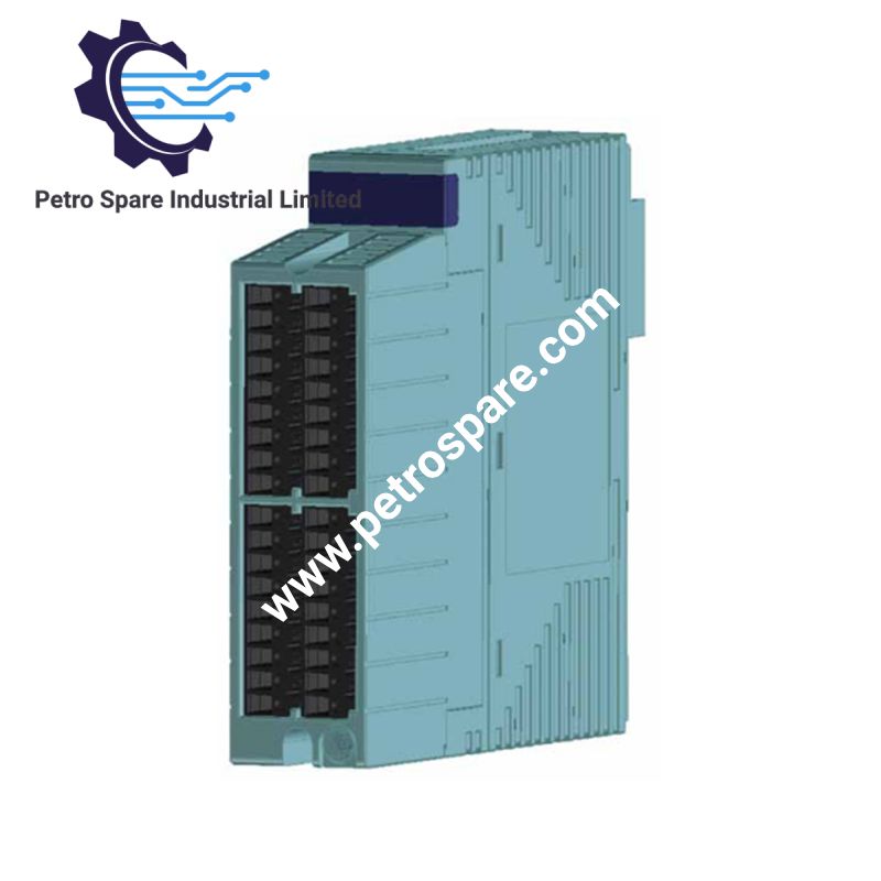
The Yokogawa NFAF135-S50 is identified as a frequency input module for industrial control system applications. It is intended for frequency-signal acquisition, where input signals are processed for use by the control system. The exact input range, channel configuration, signal characteristics, and hardware compatibility should be confirmed against the applicable NFAF135-S50 documentation before selecting a replacement or configuring a system.
Frequency Measurement and Signal Processing
The module measures the time intervals between incoming pulses and calculates their corresponding frequency. Its measurement circuit uses pulse-edge detection and interval timing, while the internal processor performs the frequency calculation. This allows the controller to obtain frequency or rotational-speed process values rather than simply counting input pulses.
Input Channels and Signal Types
The NFAF135 provides eight individually isolated input channels. It accepts the following signal types:
- Dry-contact pulse input using an open-collector contact.
- Dry-contact pulse input using a relay contact.
- Voltage pulse input using a rectangular waveform.
The input mode determines the terminal connections and associated configuration settings. For open-collector contact inputs, the maximum input frequency is limited to 800 Hz; the general 10 kHz rating should not be applied indiscriminately to every input mode.
Measurement Performance
The module covers an input frequency range of 0.1 Hz to 10 kHz, with a frequency accuracy of 0.1% of reading and a 10 ms data update cycle. The wide measurement range supports both low-speed rotational monitoring and higher-frequency pulse measurements.
Parameter Table
| Parameter | Specification |
|---|---|
| Model | NFAF135-S50 |
| Brand | Yokogawa |
| Product Type | Frequency Input Module |
| Number of Input Channels | 8 |
| Channel Isolation | Individually isolated |
| Input Signal Types | Dry-contact pulse, voltage pulse |
| Input Frequency Range | 0.1 Hz to 10 kHz |
| Maximum Frequency - Open-Collector Input | 800 Hz |
| Frequency Accuracy | 0.1% of reading |
| Data Update Cycle | 10 ms |
| Minimum Input Pulse Width | 40 us |
| Voltage Pulse Swing | 3 V or more |
| Voltage Pulse High Level | 3 to 24 VDC |
| Voltage Pulse Low Level | -1 to 8 VDC |
| Signal Source Resistance | 1 kOhm or less |
| Contact Input Open Resistance | 100 kOhm or more |
| Contact Input Closed Resistance | 200 Ohm or less |
| Transmitter Power Supply | Selectable 12 VDC / 24 VDC |
| Withstanding Voltage | 500 VAC for 1 minute, input-to-system and channel-to-channel |
Configuration and Connection Requirements
Three input modes are documented, and each requires the corresponding terminal arrangement and configuration:
- Open-collector contact: Uses INB-INC connections. The transmitter supply and shunt-resistance settings must match the field circuit.
- Relay contact: Uses INA-INB connections. This mode has a different transmitter-supply and resistance configuration from the open-collector mode.
- Voltage pulse: Uses INB-INC connections and requires the input voltage levels to remain within the specified signal limits.
The module's transmitter supply and input-mode settings are configured through the STARDOM Resource Configurator. The available 12 VDC or 24 VDC supply selection should be checked against the connected sensor's electrical requirements.
Frequently Asked Questions
Q: Can the NFAF135-S50 accept both contact pulses and voltage pulses?
A: Yes. It supports open-collector contact pulses, relay contact pulses, and rectangular voltage pulses. The selected input mode determines the wiring and configuration requirements.
Q: Can all eight channels measure frequencies up to 10 kHz?
A: The general input frequency range is 0.1 Hz to 10 kHz. However, open-collector contact input is limited to 800 Hz, so the actual operating range depends on the selected input mode.
Q: What should be checked when replacing an existing NFAF135 module?
A: Verify the complete ordering code, input signal type, channel wiring, transmitter supply setting, and controller/base-module compatibility. The model designation alone is insufficient to establish that every configuration is interchangeable.
Ordering Code and Configuration Notes
Yokogawa's product selection documentation lists NFAF135 configurations with the S50 specification code, followed by additional option codes such as 13S00, 13S10, and CCC01. Therefore, NFAF135-S50 may not represent the complete ordering code. Confirm the remaining suffix and connector configuration against the equipment nameplate before ordering.
Product Benefits
Product Benefits
- 100% genuine products in stock with fast delivery. Learn more...
- 30-day return policy for quality assurance. Learn more...
- 12-month warranty for peace of mind. Learn more...
Reviews
Reviews