

ARM55C-000
Description
Description
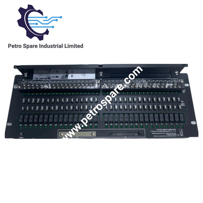
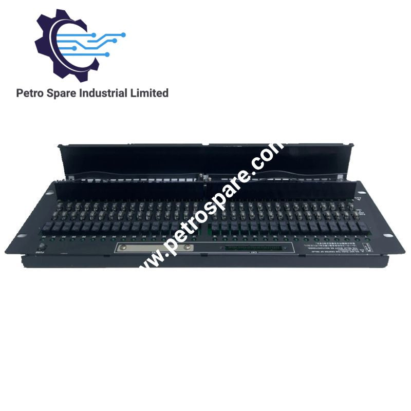
The Yokogawa ARM55C-000 is a 32-point mechanical relay board designed for dry-contact output in the CENTUM VP Field Control Unit (FIO) subsystem. It provides selectable normally open (NO) or normally closed (NC) relay contacts, allowing digital output signals to be switched to field devices through mechanical relay contacts. The -000 ordering configuration identifies the 19-inch rack-mountable basic type.
Technical Specifications
| Parameter | Specification |
|---|---|
| Model | ARM55C-000 |
| Brand | Yokogawa |
| Product Type | Mechanical Relay Board |
| Contact Points | 32 points |
| Output Type | Dry-contact relay output |
| Contact Configuration | a-contact (NO) or b-contact (NC) |
| Field Connection Terminals | M3.5 screws |
| Power Input Terminals | M4 screws |
| Mounting | 19-inch rack mountable |
| Basic Configuration | -000 |
| Parameter | Specification |
|---|---|
| Maximum Contact Load | 30 V DC, 1.5 A per point |
| Minimum Contact Load | 5 V, 10 mA |
| Internal Circuit Supply | 24 V DC |
| Internal Circuit Current Consumption | Max. 0.85 A |
| Insulation Resistance | At least 10 Mohm at 500 V DC |
| Withstanding Voltage | 2 kV AC for 1 minute (field terminals to case and 24 V terminals to field terminals) |
| Operating Temperature | 0 to 50 deg C |
| Relative Humidity | 10 to 90% RH |
| Weight | 2.2 kg |
| EMC Standards | CE, RCM, KC, EAC |
Relay Output Function
The ARM55C receives digital output signals from the ADV551 or ADV561 digital output module and switches the corresponding field circuits through mechanical relay contacts. Each of its 32 channels provides a dry-contact output, with the contact arrangement selectable as either an a-contact (normally open) or b-contact (normally closed).
Unlike the ARM55D, which provides normally open contacts, the ARM55C supports both NO and NC contact configurations. This distinction is important when matching the relay board to the field device's required switching logic.
System Configuration and Connections
The ARM55C is specified for the following CENTUM VP FIO digital output configurations:
- ADV551: 32-point digital output module with ATD5A terminal block.
- ADV561: 64-point digital output module.
- AKB331: Signal cable for 32-point configuration.
- AKB337: Signal cable for 64-point configuration.
For one ADV561 installation, Yokogawa specifies two relay boards and two AKB337 signal cables. The relay board also supports single and dual-redundant digital I/O configurations.
Contact Ratings and Electrical Requirements
The maximum rated contact load is 30 V DC at 1.5 A per point. The minimum contact load is 5 V at 10 mA. These limits should be checked against the actual field-device voltage and current requirements before selecting the relay interface.
The internal relay circuit requires an external 24 V DC supply, with maximum current consumption of 0.85 A. This supply requirement is separate from the field-side load switched by the relay contacts.
For inductive loads, Yokogawa specifies a protection circuit connected in parallel with the load: an RC circuit for AC applications or a diode for DC applications. This suppresses switching noise generated by inductive loads.
Ordering Configuration
The ARM55C-000 ordering code is identified as follows:
| Code | Description |
|---|---|
| ARM55C | 32-point mechanical relay board with dry-contact outputs |
| -0 | Always 0 |
| 0 | 19-inch rack mountable |
| 0 | Basic type |
The manufacturer also lists /BR3 for a wall-mounting bracket and /NTRY for a configuration without a cable tray. These are separate option codes and are not included in the ARM55C-000 designation.
Frequently Asked Questions
Q: Can the ARM55C-000 provide both normally open and normally closed outputs?
A: Yes. Each channel supports an a-contact (NO) or b-contact (NC) arrangement. The required contact type must be selected for the application.
Q: Which digital output modules can connect to the ARM55C-000?
A: The specified modules are ADV551 and ADV561. The corresponding signal cables are AKB331 for 32-point configurations and AKB337 for 64-point configurations.
Q: What should be checked when connecting inductive loads?
A: Check that the field load does not exceed 30 V DC and 1.5 A per point. Install an appropriate protection circuit in parallel with inductive loads, using an RC circuit for AC or a diode for DC.
Product Benefits
Product Benefits
- 100% genuine products in stock with fast delivery. Learn more...
- 30-day return policy for quality assurance. Learn more...
- 12-month warranty for peace of mind. Learn more...
Reviews
Reviews