

ANB10D-223
Description
Description
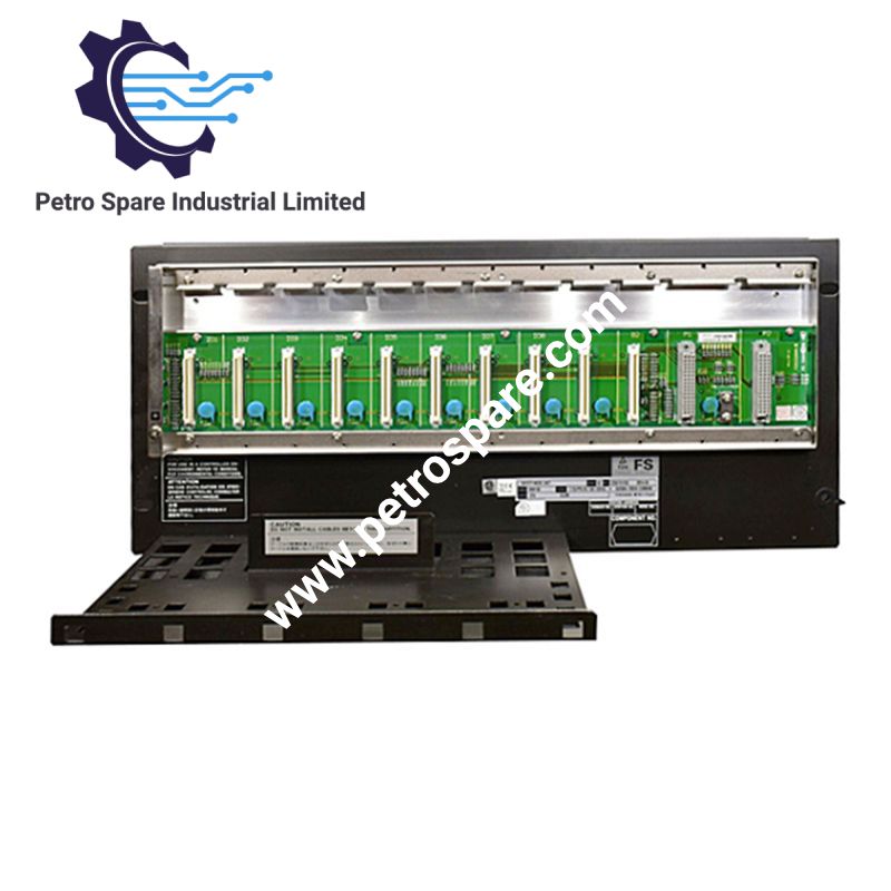
The Yokogawa ANB10S is a Single ESB Bus Node Unit used in the CENTUM VP Field Control I/O (FIO) system. It provides the communication interface between field I/O modules and a Field Control Unit (FCU) through the ESB bus, while distributing power to the installed I/O modules. Its configuration supports single or dual-redundant power supply arrangements, depending on the selected suffix code.
Function and System Configuration
The ANB10S operates as a local node connected directly to an FCU through the ESB bus. It transfers analog and contact I/O signals between the field-side modules and the control system. The node unit also provides the power distribution function required by the installed I/O modules.
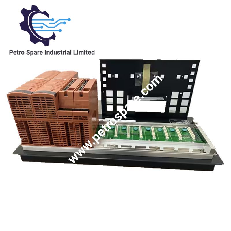
Its hardware configuration accommodates power supply modules, ESB bus interface modules and I/O modules. The single-bus designation distinguishes the ANB10S from the ANB10D, which is designed for a dual-redundant ESB bus configuration.
Power Supply and Electrical Specifications
The power supply is selected through the suffix codes. Available input options are 100-120 V AC, 220-240 V AC and 24 V DC. The specified electrical demand differs by supply type: AC configurations have separate apparent-power and active-power ratings, while the DC configuration is specified by input current.
The node unit can accommodate two power supply modules in a dual-redundant configuration. Supported power supply module models include PW481, PW482 and PW484. The power supply also provides power to field transmitters through the node unit's power distribution arrangement.
ESB Bus and I/O Module Configuration
The ANB10S connects to the FCU through an ESB Bus Coupler Module, EC401 or EC402. For a single configuration, the coupler is installed in slot 7, with slot 8 left empty. The node unit supports up to eight I/O module positions, subject to the applicable system and module allocation restrictions.
The ESB bus interface uses SB401 slave modules. Two interface modules are used when the corresponding dual-redundant configuration is selected. The installed module combination must be checked against the FCU platform and the applicable FIO or N-IO system configuration.
Model and Suffix Code Selection
The complete ordering code determines the power supply arrangement, input voltage and protection options. The following suffix selections are documented by Yokogawa for the ANB10S.
| Parameter | Specification |
|---|---|
| Model | ANB10S |
| Brand | Yokogawa |
| Product Type | Single ESB Bus Node Unit |
| System | N-IO / FIO |
| Bus Interface | Single ESB Bus |
| Power Supply Configuration | -3: Single; -4: Dual-redundant |
| AC Supply Options | 1: 100-120 V AC; 2: 220-240 V AC |
| DC Supply Option | 4: 24 V DC |
| Protection Option | 5: Basic, no explosion protection |
| Protection Option | E: Basic, with explosion protection |
| ISA G3 Option | 7: ISA Standard G3, no explosion protection |
| ISA G3 Option | G: ISA Standard G3, with explosion protection |
| Temperature Option | 6: ISA Standard G3, -20 to 70 deg C, no explosion protection |
| Temperature Option | F: ISA Standard G3, -20 to 70 deg C, with explosion protection |
| Power Consumption (100-120 V AC) | 200 VA, 120 W |
| Power Consumption (220-240 V AC) | 230 VA, 120 W |
| DC Supply Current | 5.5 A |
| Maximum I/O Module Positions | 8 |
| Mounting | 19-inch rack |
| Weight | 10 kg |
Available option codes:
- /CU1N: ESB Bus Connector Unit, part number S9562FA.
- /CU1T: ESB Bus Connector Unit with terminator, part number S9564FA.
- /ATDOC: Explosion Protection Manual.
The /ATDOC option is specified for configurations intended to comply with the ATEX Directive and UKEX Regulation. Explosion protection selection must be checked against the applicable installation requirements rather than inferred from the base model alone.
Installation Considerations
When installing FIO modules with built-in barriers, an insulating partition (part number T9083NA) must be fitted in the eighth slot. The number and allocation of I/O modules are subject to installation restrictions, including cabinet and ambient-temperature conditions.
The connector unit, power supply configuration and protection suffix should be verified against the existing node arrangement before replacement. The ANB10S and ANB10D are not interchangeable descriptions: the former is for a single ESB bus, while the latter is designed for a dual-redundant ESB bus.
Frequently Asked Questions
Q: What is the difference between Yokogawa ANB10S and ANB10D?
A: The ANB10S is a node unit for a single ESB bus, whereas the ANB10D is designed for a dual-redundant ESB bus. Their connector unit options also differ, so the complete model and connector configuration should be checked before replacement.
Q: Can the ANB10S use a dual-redundant power supply?
A: Yes. The -4 suffix specifies a dual-redundant power supply configuration. This arrangement uses two power supply modules. The -3 suffix specifies a single power supply configuration.
Q: Which connector unit is required for the ANB10S?
A: Yokogawa specifies /CU1N for the ESB Bus Connector Unit S9562FA and /CU1T for the connector unit with terminator S9564FA. The required option depends on the bus connection and termination arrangement.
Product Benefits
Product Benefits
- 100% genuine products in stock with fast delivery. Learn more...
- 30-day return policy for quality assurance. Learn more...
- 12-month warranty for peace of mind. Learn more...
Reviews
Reviews