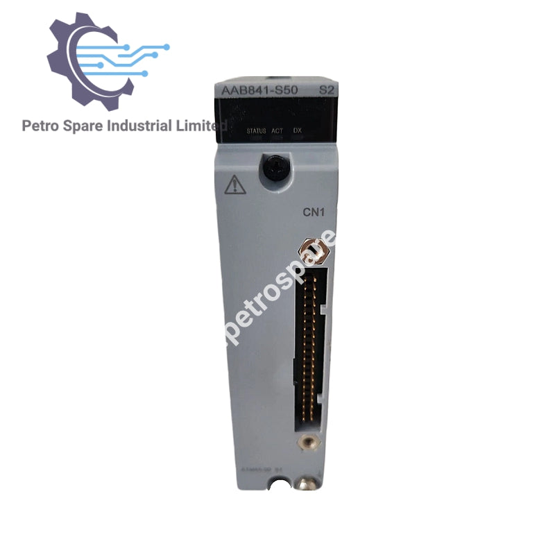


AAB841-S00
Description
Description
The Yokogawa AAB841-S00 is identified as an analog input/output module for industrial control system applications. Its exact channel configuration, signal characteristics, electrical ratings, and system interface should be verified against the applicable Yokogawa documentation before specifying it for a replacement or maintenance project.
Function and Signal Configuration
According to Yokogawa's analog I/O module specifications, the AAB841 provides 8 analog input channels and 8 analog output channels, supporting up to eight control loops. The input channels accept 1 to 5 V DC signals, while the output channels provide 4 to 20 mA DC signals. This arrangement allows the control system to acquire voltage-based process measurements and transmit current-based control commands through one module.
Input and Output Characteristics
The input section uses differential, non-isolated signal processing. Its allowable common-mode voltage is +/-1 V or less, and the specified input resistance is at least 1 MOhm when powered. The output section supports a load resistance of 0 to 750 Ohm, which should be checked against the connected field device and cable circuit.
The module provides a 10 ms data update period. Its specified input step response time is 100 ms, while the output step response time is 40 ms. These values describe different stages of signal processing and should not be treated as interchangeable response specifications.
Technical Specifications
| Parameter | Specification |
|---|---|
| Model | AAB841-S00 |
| Brand | Yokogawa |
| Product Type | Analog I/O Module |
| Input Channels | 8 |
| Output Channels | 8 |
| Input Signal | 1 to 5 V DC |
| Output Signal | 4 to 20 mA DC |
| Isolation | Non-isolated |
| Input Configuration | Differential |
| Allowable Common-Mode Voltage | +/-1 V or less |
| Allowable Input Voltage | +/-7.5 V |
| Input Resistance (Power ON) | 1 MOhm or higher |
| Input Resistance (Power OFF) | 340 kOhm or higher |
| Allowable Output Load Resistance | 0 to 750 Ohm |
| Circuit-Open Detection | Less than 0.65 mA |
| Input Accuracy | +/-4 mV |
| Output Accuracy | +/-48 uA |
| Data Update Period | 10 ms |
| Input Step Response Time | 100 ms |
| Output Step Response Time | 40 ms |
| Maximum Current Consumption | 310 mA (5 V DC), 250 mA (24 V DC) |
Installation and Signal Considerations
The non-isolated design is an important consideration when connecting the AAB841 to field instrumentation. The differential input arrangement provides a defined common-mode voltage limit, but it does not provide galvanic isolation between the field signals and the system.
Yokogawa specifies that a Zener barrier must not be connected to this module for current output applications. An isolation barrier should be used when the module is applied in intrinsically safe circuits.
Frequently Asked Questions
Q: How many field signals can the AAB841-S00 handle?
A: It provides 8 analog input channels and 8 analog output channels, supporting up to eight input/output control loops.
Q: Can the AAB841-S00 accept 4 to 20 mA input signals?
A: No. The specified input signal is 1 to 5 V DC. The 4 to 20 mA signal is used for the module's output channels. For applications requiring 4 to 20 mA input, the appropriate module specification must be checked separately.
Q: Does the AAB841-S00 provide electrical isolation?
A: No. It is a non-isolated analog I/O module. External isolation requirements must be considered when designing field signal connections, particularly for intrinsically safe applications.
Product Benefits
Product Benefits
- 100% genuine products in stock with fast delivery. Learn more...
- 30-day return policy for quality assurance. Learn more...
- 12-month warranty for peace of mind. Learn more...
Reviews
Reviews