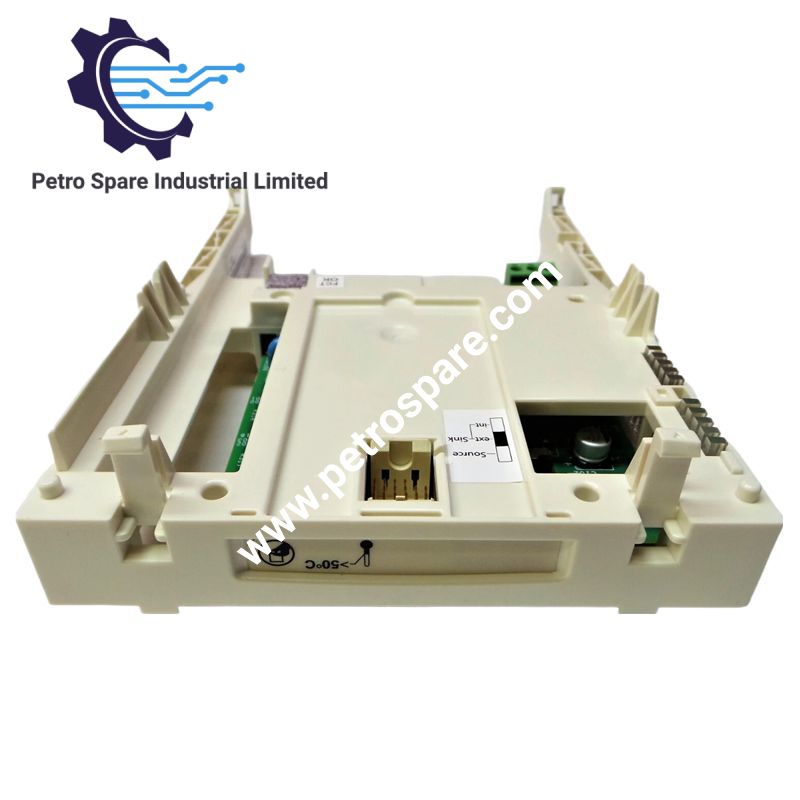
VW3A3201
Description
Description
The Schneider Electric VW3A3201, also cataloged as the VW3A3201 logic I/O card, provides additional discrete input, relay output, logic output, and PTC thermistor probe connections for Altivar 61 and Altivar 71 variable speed drives. It supports configurable logic signals, relay switching, and motor thermal protection through dedicated terminal connections.
Hardware Specifications
| Parameter | Specification |
|---|---|
| Model | VW3A3201 |
| Brand | Schneider Electric |
| Product Type | Logic I/O Card |
| Compatible Drives | Altivar 61, Altivar 71, Altivar Lift, Altivar 61Q, Altivar 71Q |
| Weight | 0.3 kg |
| Discrete Inputs | 4 programmable inputs, LI7-LI10 |
| Discrete Outputs | 5 total: configurable relay outputs R3A, R3B, R3C and assignable logic outputs LO1, LO2 |
| Logic Output Voltage | 24 VDC, operating limits 12-30 V |
| Logic Output Current | Maximum 0.2 A per assignable logic output |
| Programmable Input Voltage | 24 VDC, maximum 30 V |
| Input Impedance | 3.5 kOhm |
| Input Sampling Time | 1.5-2.5 ms |
| Logic Output Sampling Time | 1.5-2.5 ms |
| Reference Potentiometer Supply | 10.5 VDC, range 10-11 V, maximum 0.01 A |
| Auxiliary Supply | 24 VDC, range 21-27 V, maximum 0.2 A |
| Relay Contact Rating | Maximum 5 A at 250 VAC or 30 VDC for resistive loads; 2 A at 250 VAC or 30 VDC for specified inductive loads |
| Minimum Relay Switching Current | 3 mA at 24 VDC |
| Relay Electrical Durability | 100,000 cycles |
| PTC Probe Input | TH1+, TH1-; supports up to 6 PTC probes under specified impedance conditions |
| Terminal Connection | 1.5 mm2 / AWG 16 |
| Terminal Tightening Torque | 0.25 N.m |
Discrete I/O and Motor Thermal Protection
The VW3A3201 adds four programmable discrete inputs and two assignable logic outputs to compatible Altivar drives. The LI7-LI10 inputs support positive or negative logic, with different voltage thresholds for each configuration. The LO1 and LO2 outputs also support positive or negative logic assignment.
The R3A, R3B, and R3C terminals provide configurable relay logic connections. Relay switching limits depend on load type: resistive loads permit up to 5 A under the specified voltage conditions, while the stated inductive-load limit is 2 A.
The TH1+ and TH1- terminals provide a PTC thermistor probe input for motor thermal monitoring. The specified trip resistance is 3 kOhm, and the reset resistance is 1.8 kOhm. The card also specifies short-circuit detection at an impedance below 0.05 Ohm and support for six PTC probes under the stated impedance condition.
Frequently Asked Questions
Q: Which drives support the VW3A3201 logic I/O card?
A: The listed compatible ranges are Altivar 61, Altivar 71, Altivar Lift, Altivar 61Q, and Altivar 71Q. Verify the specific drive reference and hardware configuration before installation.
Q: What are the relay output switching limits?
A: For resistive loads, the specified maximum is 5 A at 250 VAC or 30 VDC. For inductive loads with the stated power factor and time constant, the maximum is 2 A at 250 VAC or 30 VDC. The minimum switching current is 3 mA at 24 VDC.
Q: Can the VW3A3201 monitor PTC thermistor probes?
A: Yes. The TH1+ and TH1- terminals accept a PTC probe circuit. The specifications include a 3 kOhm trip resistance, a 1.8 kOhm reset resistance, and support for up to six probes subject to the specified impedance limit.
Field Installation Guidelines
- Isolate the drive from all power sources and verify that the DC bus has discharged according to the drive manufacturer's instructions before installing or removing the card.
- Confirm compatibility with the specific Altivar drive model and hardware revision.
- Install the card in the designated drive option-card position, following the manufacturer's mechanical assembly instructions.
- Connect discrete input and output wiring to the designated terminals. Verify positive or negative logic configuration against the drive control settings.
- Keep low-level control wiring separated from motor cables and other high-noise power conductors.
- Use appropriately rated conductors and observe the specified terminal cross-section of 1.5 mm2 / AWG 16 and tightening torque of 0.25 N.m.
- Check relay contact ratings against the connected load. Use external suppression where required for inductive loads and permitted by the load and drive manufacturer's instructions.
- Connect PTC thermistor wiring to TH1+ and TH1-. Verify the probe circuit resistance and wiring continuity before enabling the drive.
- Inspect terminal tightness, insulation, and grounding arrangements before energizing the system.
- Verify input states, logic output operation, relay switching, and PTC monitoring during commissioning.
Product Benefits
Product Benefits
- 100% genuine products in stock with fast delivery. Learn more...
- 30-day return policy for quality assurance. Learn more...
- 12-month warranty for peace of mind. Learn more...
Reviews
Reviews