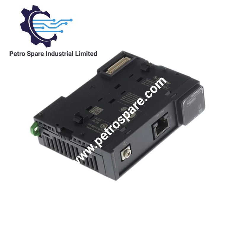
TM3XTRA1
Description
Description
The Schneider Electric TM3XTRA1, also cataloged as the TM3XTRA1 remote transmitter module, extends the Modicon TM3 expansion bus between a compatible logic controller and a remote bus receiver. It uses an RJ45 connection for the bus expansion cable and a screw terminal for functional ground. The module operates with Modicon M221, M241, M251, and M262 controllers and has a maximum power dissipation of 0.6 W.
Hardware Specifications
| Parameter | Specification |
|---|---|
| Model | TM3XTRA1 |
| Brand | Schneider Electric |
| Product Range | Modicon TM3 |
| Product Type | Remote Transmitter Module |
| Compatible Controllers | Modicon M221, M241, M251, M262 |
| Bus Connection | RJ45 connector |
| Ground Connection | Screw connector terminal |
| Extension Cable | 2 RJ45 connectors; specified distance range requires manufacturer clarification |
| Current Consumption | 100 mA at 5 VDC (state on); 30 mA at 5 VDC (state off) |
| Maximum Power Dissipation | 0.6 W |
| Local Signalling | 1 green power LED; 1 green Link LED |
| Mounting | TH35-15 DIN rail, TH35-7.5 DIN rail, or panel mounting with fixing kit |
| Dimensions (W x D x H) | 23.65 x 73.3 x 90 mm |
| Weight | 0.065 kg |
| Operating Temperature | -10 to 55 deg C (horizontal); -10 to 50 deg C (vertical) |
| Storage Temperature | -40 to 70 deg C |
| Relative Humidity | 5 to 95%, non-condensing |
| Operating Altitude | 0 to 2000 m |
| Protection Rating | IP20 |
| Pollution Degree | 2 |
| Shock Resistance | 15 gn for 11 ms |
| Vibration Resistance | 3.5 mm at 5 to 8.4 Hz; 3 gn at 8.4 to 150 Hz |
| Environmental Footprint | 27 kg CO2 eq. |
| Certifications and Markings | CE, UKCA, RCM, EAC, cULus, CSA HazLoc, GOST, Merchant Navy, C-Tick |
TM3 Expansion Bus Communication and Electrical Characteristics
The TM3XTRA1 transfers expansion bus communication between the local controller-side assembly and a remote bus receiver through an RJ45-connected extension cable. The TM3 expansion system uses a bus connector to distribute data and power between interconnected modules.
The module specifies two 5 VDC bus-connector current-consumption states: 100 mA when on and 30 mA when off. Its maximum power dissipation is 0.6 W. These figures describe different electrical parameters and should not be treated as interchangeable.
The green power LED indicates the module's power status, while the green Link LED indicates link status. The enclosure has an IP20 protection rating and is intended for installation inside a suitable electrical enclosure.
Frequently Asked Questions (FAQ)
Q: Which Modicon controllers are compatible with the TM3XTRA1?
A: The module is specified for Modicon M221, M241, M251, and M262 logic controllers.
Q: What are the electrical consumption requirements of the TM3XTRA1?
A: The specified current consumption through the 5 VDC bus connector is 100 mA in the on state and 30 mA in the off state. Maximum power dissipation is 0.6 W.
Q: Can the TM3XTRA1 be installed in a vertical orientation?
A: Yes. The specified operating temperature range is -10 to 50 deg C for vertical installation and -10 to 55 deg C for horizontal installation.
Field Installation Guidelines
- Mounting: Install the module on a TH35-15 or TH35-7.5 DIN rail conforming to IEC 60715, or use a suitable panel mounting arrangement with the specified fixing kit.
- Bus wiring: Connect the extension cable to the designated RJ45 interface and the compatible remote bus receiver. Confirm the cable specification and permitted length in the official installation guide before commissioning.
- Functional ground: Connect the functional ground through the screw terminal using the manufacturer's wiring instructions.
- Power and communication checks: Verify the module's power supply and inspect the green power and Link LEDs during commissioning.
- Thermal management: Maintain the applicable operating temperature limit for the selected mounting orientation. Account for heat generated by adjacent modules and enclosure equipment.
- Environmental protection: Install the IP20 module in an enclosure appropriate for the site's dust, moisture, and electrical protection requirements.
- Electromagnetic compatibility: Route bus cables separately from high-current and switching-power conductors where practical. Apply the manufacturer's grounding and cable-routing requirements to reduce electromagnetic interference.
- Mechanical security: Confirm that the module is fully engaged with the mounting rail or fixing arrangement and that all cable connections are secure before energizing the system.
Product Benefits
Product Benefits
- 100% genuine products in stock with fast delivery. Learn more...
- 30-day return policy for quality assurance. Learn more...
- 12-month warranty for peace of mind. Learn more...
Reviews
Reviews