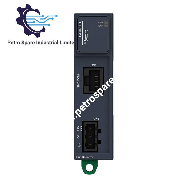
TM3XREC1
Description
Description
Configured for remote I/O expansion in Modicon M221, M241, M251, and M262 controller systems, the Schneider Electric TM3XREC1 (TM3XREC1 Remote Receiver Module) receives bus connections from a remote transmitter through an RJ45 expansion cable. It supports up to 7 I/O expansion modules, operates with a 24 VDC supply, and distributes bus data and power through the Modicon TM3 expansion interface.
Hardware Specifications
| Parameter | Specification |
|---|---|
| Model | TM3XREC1 |
| Brand | Schneider Electric |
| Product Range | Modicon TM3 |
| Product Type | Remote Receiver Module |
| Compatible Controllers | Modicon M221, M241, M251, M262 |
| Maximum I/O Expansion Modules | 7 |
| Rated Supply Voltage | 24 VDC, external supply |
| Supply Voltage Tolerance | -15% to +20% |
| Current Consumption | 40 mA at 24 VDC via bus connector |
| Expansion Bus Output Current | 560 mA at 5 V; 560 mA at 24 V |
| Maximum Power Dissipation | 1 W |
| Electrical Connections | RJ45 bus transmitter connector; removable 3-terminal screw block for 24 VDC supply |
| Status Indicators | Green power LED; green Link LED |
| Protection Rating | IP20 |
| Mounting | TH35-15 or TH35-7.5 DIN rail; plate or panel with fixing kit |
| Dimensions (W x D x H) | 23.65 x 73.3 x 90 mm |
| Weight | 0.075 kg |
| Operating Temperature | -10 to 55 deg C horizontal; -10 to 50 deg C vertical |
| Storage Temperature | -40 to 70 deg C |
| Relative Humidity | 5% to 95%, non-condensing |
| Operating Altitude | 0 to 2000 m |
| Pollution Degree | 2 |
| Vibration Resistance | 3.5 mm at 5-8.4 Hz; 3 gn at 8.4-150 Hz |
| Shock Resistance | 15 gn for 11 ms |
| Electromagnetic Compatibility | IEC 55011 Class A radiated emissions |
| Standards | IEC 61131-2, UL 508, CSA C22.2 No. 142, UL 1604, CSA C22.2 No. 213 |
| Certifications and Markings | CE, UKCA, RCM, EAC, cULus, CSA HazLoc, GOST, Merchant Navy, C-Tick |
| Lifecycle Carbon Footprint | 21 kg CO2 eq. |
Remote I/O Bus Communication and Power Distribution
The TM3XREC1 provides the receiver-side interface for remote Modicon TM3 I/O expansion. An RJ45 connection links the receiver to the bus transmitter, while the removable screw terminal block connects the external 24 VDC supply.
The expansion bus distributes data and power between compatible controller and I/O components. The specified maximum expansion count is 7 modules. The receiver's 40 mA current consumption and 1 W maximum power dissipation should be considered when checking the electrical load and thermal conditions of the installation.
The listed expansion bus output current ratings are 560 mA at 5 V and 560 mA at 24 V. These ratings should not be interpreted as proof that both supplies can deliver their maximum rated currents simultaneously under every system configuration.
Frequently Asked Questions (FAQ)
Q: Which Modicon controllers are compatible with the TM3XREC1?
A: The module is listed for use with Modicon M221, M241, M251, and M262 logic controllers. Confirm the controller hardware and configuration requirements before commissioning.
Q: What power supply and current consumption does the receiver require?
A: The rated supply is 24 VDC, with a tolerance of -15% to +20%. The specified current consumption is 40 mA at 24 VDC via the bus connector, and maximum power dissipation is 1 W.
Q: What installation conditions must be observed?
A: Maintain the specified operating temperature for the mounting orientation: -10 to 55 deg C horizontally or -10 to 50 deg C vertically. The enclosure rating is IP20, so the module requires installation in an environment that provides appropriate protection against dust and water ingress.
Field Installation Guidelines
- Mounting: Install the receiver on a compatible TH35-15 or TH35-7.5 DIN rail, or use the specified plate or panel fixing kit. Secure the module before connecting field wiring.
- Power wiring: Connect the external 24 VDC supply through the removable 3-terminal screw block. Verify polarity and supply voltage before energizing the assembly.
- Bus connection: Connect the RJ45 interface to the corresponding bus transmitter using the designated expansion cable. Verify the cable specification and permitted routing against the Schneider Electric installation documentation; the supplied data does not establish an unambiguous cable-length limit.
- Grounding and shielding: Follow the controller and cable manufacturer's grounding and shielding instructions. Keep communication wiring separated from high-current switching conductors where practical to reduce electromagnetic interference.
- Thermal clearance: Observe the operating temperature limits for the selected mounting orientation. Avoid installation adjacent to components that produce excessive heat.
- Commissioning: Check the green power and Link LEDs after energizing. Verify the controller configuration, expansion-module count, bus communication, and I/O status before enabling the controlled process.
- Environmental protection: The IP20 enclosure is intended for protected installation. Prevent conductive contamination, condensation, and exposure to liquids.
Product Benefits
Product Benefits
- 100% genuine products in stock with fast delivery. Learn more...
- 30-day return policy for quality assurance. Learn more...
- 12-month warranty for peace of mind. Learn more...
Reviews
Reviews