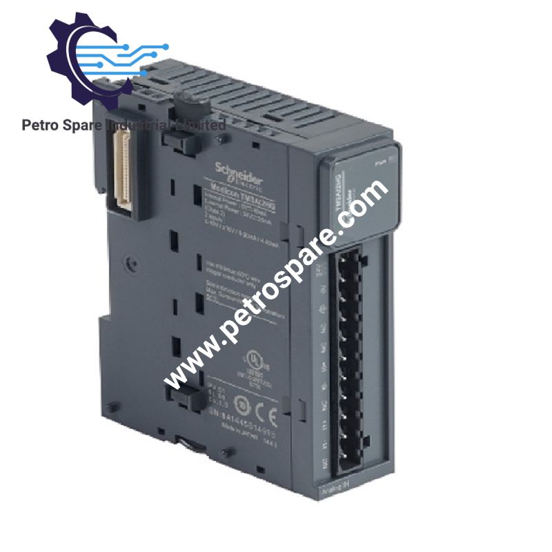
TM3TI4
Description
Description
The Schneider Electric TM3TI4, also cataloged as the TM3TI4 analog input module, provides four configurable analog channels for voltage, current, thermocouple, and resistance temperature sensor acquisition within Modicon M221, M241, M251, and M262 control systems. It supports 16-bit and 15-bit plus sign resolution, removable screw terminals, and 24 VDC external supply.
Hardware Specifications
| Parameter | Specification |
|---|---|
| Model | TM3TI4 |
| Brand | Schneider Electric |
| Product Range | Modicon TM3 |
| Product Type | Analog Input Module |
| Origin | Not specified in the supplied data |
| Number of Inputs | 4 analog inputs |
| Input Types | 0-20 mA, 4-20 mA, 0-10 V, -10 to +10 V, thermocouples, Pt100, Pt1000, Ni100, Ni1000 |
| Resolution | 16 bits; 15 bits + sign |
| Sampling Duration | 10 ms |
| Thermocouple Conversion Time | 100 ms + 100 ms per channel + one controller cycle |
| Accuracy | Typically +/-0.2% of full scale at 25 deg C for voltage/current inputs; varies by sensor type and range |
| Repeat Accuracy | +/-0.5% FS |
| Cross Talk | <= 1 LSB |
| External Supply | 24 VDC |
| Current Consumption | 35 mA typical at 24 VDC; 45 mA typical at 5 VDC via bus connector |
| Electrical Connection | Removable screw terminal block, 3.81 mm pitch |
| Cable Type | Twisted shielded pairs, less than 30 m for input circuits |
| Input Impedance | <= 50 Ohm for current inputs; >= 1 MOhm for voltage inputs |
| Input-to-Supply Insulation | 1500 V AC |
| Input-to-Internal Logic Insulation | 500 V AC |
| Immunity to Microbreaks | 10 ms |
| Mounting | TH35-15 or TH35-7.5 DIN rail; plate or panel with fixing kit |
| Dimensions (H x W x D) | 90 x 23.6 x 70 mm |
| Weight | 0.11 kg |
| Operating Temp | -10 to 55 deg C horizontal; -10 to 35 deg C vertical |
| Storage Temperature | -25 to 70 deg C |
| Protection Rating | IP20 |
| Relative Humidity | 10-95%, non-condensing |
| Operating Altitude | 0-2000 m |
| Standards | IEC 61131-2 |
| Certifications | CE, UKCA, RCM, EAC, cULus, cULus HazLoc |
| Environmental Footprint | 83 kg CO2 eq. |
Analog Signal Acquisition and PLC Integration
The TM3TI4 accepts current, voltage, thermocouple, and resistance temperature sensor signals through four analog input channels. Supported thermocouple types include J, K, R, S, B, T, N, E, and C. Temperature probe types include Pt100, Pt1000, Ni100, and Ni1000.
The module communicates with the compatible logic controller through the Modicon TM3 bus expansion connector, which distributes data and bus power. Its 3.81 mm pitch removable screw terminals provide field wiring connections. The module supports a maximum continuous overload of 40 mA for current inputs and 13 V for voltage inputs.
The stated temperature drift is +/-0.01% FS/deg C, and non-linearity is +/-0.2% FS. Actual measurement accuracy depends on the selected input type and operating range.
Frequently Asked Questions
Q: Which PLC platforms support the TM3TI4?
A: The module is compatible with Modicon M221, M241, M251, and M262 logic controllers. Confirm controller configuration and software compatibility before installation.
Q: What wiring is specified for the analog input circuits?
A: Twisted shielded-pair cable shorter than 30 m is specified for input circuits. Separate analog signal wiring from power and switching conductors, and terminate cable shields according to the installation grounding design.
Q: Can the TM3TI4 be installed vertically?
A: Yes. The specified operating temperature range is -10 to 35 deg C for vertical installation, compared with -10 to 55 deg C for horizontal installation.
Field Installation Guidelines
- Mounting: Install the module on a TH35-15 or TH35-7.5 DIN rail conforming to IEC 60715, or use the specified plate or panel fixing kit.
- Bus connection: Align and secure the TM3 expansion connector with the compatible controller or adjacent expansion module. Verify the assembly interlock is engaged.
- Field wiring: Connect each analog input to the appropriate removable screw terminal. Verify signal polarity, input type, and configured measurement range before energizing the circuit.
- Cable routing: Use twisted shielded pairs shorter than 30 m. Route low-level analog wiring separately from motor cables, contactor wiring, and other sources of electrical interference.
- Shield grounding: Apply the site grounding and EMC design for shield termination. Avoid unintended ground loops and verify protective grounding arrangements.
- Power supply: Verify the external 24 VDC supply and bus power connections against the controller and module wiring documentation. Check terminal tightness before commissioning.
- Environmental limits: Maintain the applicable horizontal or vertical operating temperature limit. The module has an IP20 enclosure rating and requires installation in an environment that provides appropriate protection against dust and moisture.
- Commissioning: Configure each channel for the connected sensor or signal type. Verify raw input values, scaling, sensor wiring, and controller diagnostics before enabling closed-loop control.
Product Benefits
Product Benefits
- 100% genuine products in stock with fast delivery. Learn more...
- 30-day return policy for quality assurance. Learn more...
- 12-month warranty for peace of mind. Learn more...
Reviews
Reviews