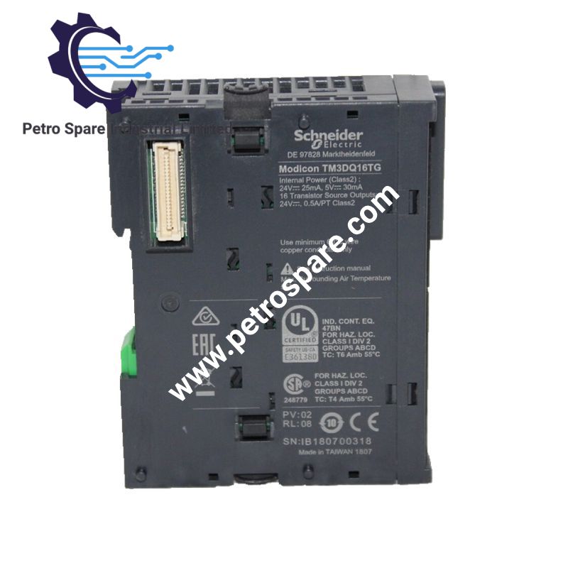
TM3DQ16TG
Description
Description
The Schneider Electric TM3DQ16TG, also cataloged as the TM3DQ16TG discrete output module, provides 16 transistor PNP source outputs for controlling external devices from Modicon M221, M241, M251, and M262 controllers. It operates at 24 VDC and uses a bus connector for internal power and data distribution. Removable spring terminals provide field wiring connections, and individual green LEDs indicate output status.
Hardware Specifications
| Parameter | Specification |
|---|---|
| Model | TM3DQ16TG |
| Brand | Schneider Electric |
| Product Range | Modicon TM3 |
| Product Type | Discrete Output Module |
| Weight | 0.11 kg |
| Dimensions | 27.4 x 84.6 x 90 mm (W x D x H) |
| Operating Temp | -10 to 35 deg C (vertical); -10 to 55 deg C (horizontal) |
| Power Consumption | Internal bus powered; typical current consumption listed as 5 mA at 5 VDC and 10 mA at 24 VDC |
| Number of Outputs | 16 transistor outputs |
| Output Logic | Positive logic (PNP source) |
| Output Voltage | 24 VDC |
| Output Current | 500 mA per transistor output |
| Output Response Time | 450 us maximum, turn-on and turn-off |
| Maximum Leakage Current | 0.1 mA |
| Maximum Voltage Drop | Less than 0.4 V |
| Output-to-Bus Isolation | 500 VAC |
| Output-to-Supply Isolation | 1500 VAC |
| Electrical Connection | Removable spring terminal block, 3.81 mm pitch |
| Maximum Unshielded Cable Distance | 30 m |
| Protection Rating | IP20 |
| Mounting | TH35-7.5 or TH35-15 DIN rail, or panel mounting with fixing kit |
| Storage Temperature | -25 to 70 deg C |
| Relative Humidity | 10-95%, non-condensing |
| Standards | IEC 61131-2 |
| Certifications | CE, cULus, UKCA, RCM, EAC, cULus HazLoc |
| GTIN | 3606480611490 |
| Lifecycle Carbon Footprint | 34 kg CO2 eq. |
PNP Output Architecture and PLC Integration
The TM3DQ16TG uses positive-logic transistor outputs to switch the positive supply to connected loads. Each channel supports a specified output current of up to 500 mA. The connected load current, supply voltage, and total system loading must remain within the applicable hardware limits.
The module connects to compatible Modicon M221, M241, M251, and M262 controllers through the TM3 expansion bus. The bus distributes internal power and data between assembled modules. EcoStruxure Machine Expert supports controller programming and configuration of the expansion I/O system.
Each output has an individual green status LED. The 500 VAC isolation rating between channels and bus and the 1500 VAC isolation rating between output and supply are separate specifications and should not be treated as interchangeable.
Frequently Asked Questions (FAQ)
Q: What is the maximum current per output channel?
A: The specified maximum transistor output current is 500 mA per channel. Verify the load requirements and applicable module loading limits before connecting multiple outputs to external devices.
Q: Which PLC controllers support the TM3DQ16TG?
A: The module is listed as compatible with Modicon M221, M241, M251, and M262 logic controllers. Confirm the controller configuration and firmware compatibility before installation.
Q: Can the TM3DQ16TG be installed on a DIN rail?
A: Yes. It supports TH35-7.5 and TH35-15 rails conforming to IEC 60715. Panel mounting is also supported when the appropriate fixing kit is used.
Field Installation Guidelines
- Isolate the controller and external load supplies before mounting the module or wiring the output terminals.
- Install the module on a compatible DIN rail or panel and engage the TM3 interlocking mechanism according to the manufacturer's instructions.
- Connect the module to the controller expansion bus and verify that the bus connectors are fully seated.
- Wire each PNP output according to the terminal assignment in the official instruction sheet. Confirm the load supply polarity and common reference before energizing the circuit.
- Use conductors within the specified 0.14-1.5 mm2 range. Secure each spring terminal connection and check for exposed conductor strands.
- Keep output wiring separated from high-noise power conductors where practical. Apply appropriate shielding and grounding practices to minimize electromagnetic interference.
- Keep the installation within the applicable ambient temperature, humidity, and cable-length limits. The specified maximum unshielded output cable distance is 30 m.
- After energization, verify each channel's LED indication and confirm the corresponding field device switches as commanded by the PLC.
- Consult the official product datasheet and instruction sheet for terminal assignments, load restrictions, and commissioning requirements.
Product Benefits
Product Benefits
- 100% genuine products in stock with fast delivery. Learn more...
- 30-day return policy for quality assurance. Learn more...
- 12-month warranty for peace of mind. Learn more...
Reviews
Reviews