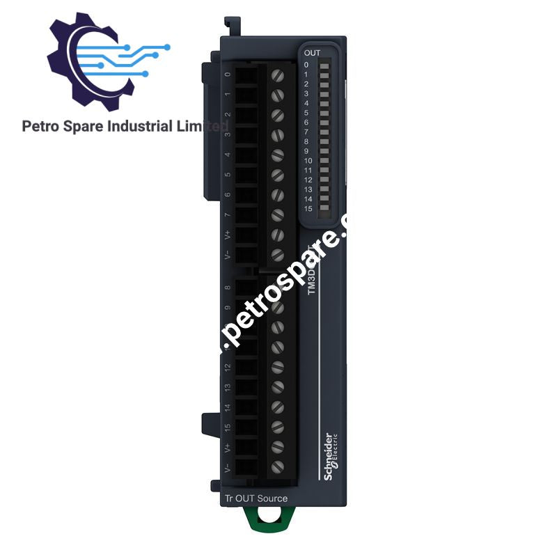
TM3DQ16T
Description
Description
The Schneider Electric TM3DQ16T, also cataloged as the TM3DQ16T discrete output module, provides 16 transistor PNP source outputs for 24 VDC control signals in Modicon M221, M241, M251, and M262 PLC systems. It uses a bus expansion connector for internal power and data distribution and removable screw terminals for field wiring. The module supports switching external control devices, including variable speed drives and equipment with compatible current or voltage inputs.
Hardware Specifications
| Parameter | Specification |
|---|---|
| Model | TM3DQ16T |
| Brand | Schneider Electric |
| Product Series | Modicon TM3 |
| Product Type | Discrete Output Module |
| Weight | 0.105 kg |
| Dimensions | 27.4 x 84.6 x 90 mm (W x D x H) |
| Operating Temp | -10 to 35 deg C (vertical); -10 to 55 deg C (horizontal) |
| Storage Temperature | -25 to 70 deg C |
| Power Consumption | Internal bus powered; typical current consumption varies by supply rail |
| Number of Outputs | 16 transistor outputs |
| Output Logic | Positive logic (source/PNP) |
| Rated Output Voltage | 24 VDC |
| Maximum Output Current | 500 mA per transistor output |
| Maximum Turn-On Response Time | 450 us |
| Maximum Turn-Off Response Time | 450 us |
| Maximum Leakage Current | 0.1 mA |
| Maximum Voltage Drop | Less than 0.4 V |
| Output-to-Bus Isolation | 500 VAC |
| Output-to-Output Isolation | Non-insulated |
| Electrical Connection | Removable screw terminal block, 3.81 mm pitch |
| Cable Cross-Section | 0.14 to 1.5 mm2 |
| Maximum Cable Distance | 30 m with unshielded cable |
| Local Indication | One green LED per output channel |
| Protection Rating | IP20 |
| Mounting | TH35-7.5 / TH35-15 DIN rail or panel mounting |
| Relative Humidity | 10 to 95%, non-condensing |
| Maximum Operating Altitude | 2000 m |
| Standards | IEC 61131-2 |
| Certifications | CE, cULus, UKCA, RCM, EAC, cULus HazLoc |
| Compatible Controllers | Modicon M221, M241, M251, M262 |
| Programming Software | EcoStruxure Machine Expert |
| GTIN | 3606480611483 |
| Lifecycle Carbon Footprint | 33 kg CO2 eq. |
PNP Output Switching and PLC Bus Integration
The TM3DQ16T uses positive-logic transistor outputs to source current to connected loads. Each output supports a maximum current of 500 mA, subject to the applicable module and installation load constraints. The maximum specified switching response time is 450 us for both turn-on and turn-off transitions.
The module receives internal power and data through the TM3 bus expansion connector. Its output circuits provide 500 VAC isolation from the bus, while the individual output channels are not isolated from one another. External load wiring must therefore account for shared electrical references and the common supply arrangement.
Each output has a dedicated green status LED. The removable screw terminal block supports field wiring with conductor cross-sections from 0.14 to 1.5 mm2.
Frequently Asked Questions (FAQ)
Q: Can the TM3DQ16T directly drive a variable speed drive?
A: It can provide control signals to a drive with compatible current or voltage input requirements. Verify the drive input interface, signal common, and electrical ratings before connecting it. The module is not a power output stage for supplying a drive's motor.
Q: Are the 16 output channels galvanically isolated from each other?
A: No. The outputs are not isolated from one another. The specified 500 VAC isolation applies between the output circuits and the internal bus. External wiring must account for this distinction.
Q: What are the mounting and operating-temperature requirements?
A: The module supports TH35-7.5 or TH35-15 DIN rail mounting and panel mounting with a fixing kit. The specified operating range is -10 to 35 deg C for vertical installation and -10 to 55 deg C for horizontal installation.
Field Installation Guidelines
- Mounting: Install the module on a compatible DIN rail or panel using the specified mounting arrangement. Maintain the required clearances and ventilation conditions of the controller assembly.
- Bus connection: Align and engage the TM3 expansion connector with the adjacent controller or expansion module. Confirm mechanical engagement before applying power.
- Field wiring: Connect the 24 VDC PNP outputs to compatible load inputs. Verify polarity, common reference, load current, and the electrical requirements of each connected device.
- Terminal tightening: Use the terminal manufacturer's specified tightening torque. Do not exceed the permitted conductor cross-section.
- Cable routing: Separate output wiring from high-voltage power conductors and high-noise switching circuits where practical. Use appropriate shielding and grounding practices for the connected equipment.
- Cable length: Keep unshielded output cables within the specified 30 m maximum.
- Commissioning: Verify channel assignments in the PLC program, inspect wiring for shorts and polarity errors, and test each output under controlled conditions. Confirm that the connected load remains within its electrical limits.
- Environmental conditions: Maintain the applicable temperature and humidity limits. The IP20 rating does not provide protection against water ingress or conductive contamination.
Product Benefits
Product Benefits
- 100% genuine products in stock with fast delivery. Learn more...
- 30-day return policy for quality assurance. Learn more...
- 12-month warranty for peace of mind. Learn more...
Reviews
Reviews