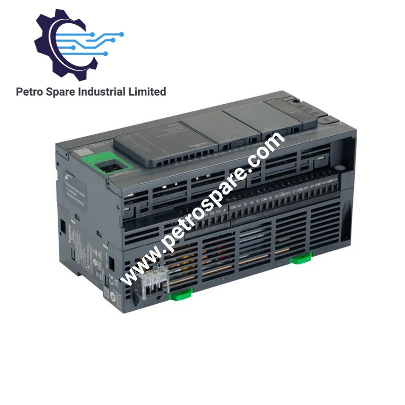
TM241CE40R
Description
Description
Configured for discrete I/O processing and Ethernet-based machine communication in the Modicon M241 platform, the Schneider Electric TM241CE40R (TM241CE40R logic controller) provides direct physical and electrical control through 40 integrated I/O points, relay and transistor outputs, serial interfaces, USB, and 10/100 Mbit/s Ethernet.
Hardware Specifications
| Parameter | Specification |
|---|---|
| Model | TM241CE40R |
| Brand | Schneider Electric |
| Series | Modicon M241 |
| Product Type | Logic controller |
| Weight | 0.62 kg |
| Dimensions | 190 x 95 x 90 mm (W x D x H) |
| Operating Temp | -10 to 50 deg C vertical; -10 to 55 deg C horizontal |
| Rated Supply Voltage | 100 to 240 VAC |
| Supply Voltage Limits | 85 to 264 VAC |
| Network Frequency | 50/60 Hz |
| Discrete I/O | 40 |
| Discrete Inputs | 24 standard inputs, including 8 fast inputs |
| Discrete Input Voltage | 24 VDC |
| Discrete Input Current | 7 mA |
| Discrete Outputs | 12 relay, 4 transistor, including 4 fast outputs |
| Relay Output Voltage | 5 to 125 VDC; 5 to 250 VAC |
| Relay Output Current | 2 A |
| Transistor Output Voltage | 24 VDC |
| Transistor Output Current | 0.5 A |
| Fast Output Current | 0.1 A |
| Maximum Fast Output Frequency | 20 kHz PWM; 100 kHz PLS |
| High-Speed Counter Inputs | 4 at up to 200 kHz |
| Positioning Outputs | 4 PTO channels, up to 100 kHz |
| Program Memory | 8 MB |
| System Memory | 64 MB RAM |
| Built-in Flash | 128 MB for user program backup |
| Optional SD Card | Up to 16 GB |
| Ethernet | 10BASE-T/100BASE-TX |
| Ethernet Protocols | Modbus TCP, EtherNet/IP, OPC UA |
| Serial Link 1 | RJ45, RS232/RS485, non-isolated |
| Serial Link 2 | Removable terminal block, RS485, non-isolated |
| USB | Mini-B USB 2.0 |
| Modbus Transmission Rate | 1.2 to 115.2 kbit/s |
| Ethernet Transmission Rate | 10/100 Mbit/s |
| Local I/O Expansion | Up to 7 modules |
| Remote I/O Expansion | Up to 14 modules |
| Mounting | TH35-15 or TH35-7.5 DIN rail; panel mounting with fixing kit |
| Protection Rating | IP20 |
| Insulation | 500 VAC between supply and internal logic |
| Sensor Supply | 24 VDC, 400 mA |
| Surge Withstand | Up to 2 kV depending on circuit and test mode |
| Relative Humidity | 10 to 95%, non-condensing |
| Operating Altitude | 0 to 2000 m |
| Certifications | CE, cULus, RCM, UKCA, DNV-GL, ABS, LR |
Ethernet Communication and I/O Scaling
The TM241CE40R integrates 40 discrete I/O points with 24 inputs and 16 outputs. The output section combines relay and transistor circuits, allowing separate handling of switching loads and high-speed pulse functions. Four fast inputs support high-speed counter operation up to 200 kHz, while four PTO channels support positioning signals up to 100 kHz.
The Ethernet interface operates at 10/100 Mbit/s and provides Modbus TCP and EtherNet/IP functions. The controller supports Modbus TCP client and server functions, EtherNet/IP target and originator I/O scanning, FTP, SNMP, DHCP, firmware updating, web services, and OPC UA server functions. Up to 64 Modbus TCP devices and 16 EtherNet/IP devices are specified.
Serial communication uses two non-isolated links. Serial Link 1 provides selectable RS232/RS485 through an RJ45 connector, while Serial Link 2 provides RS485 through a removable screw terminal block. Modbus master/slave communication is supported at up to 115.2 kbit/s.
Frequently Asked Questions
Q: What is the I/O arrangement of the TM241CE40R?
A: The controller has 40 integrated discrete I/O points: 24 inputs and 16 outputs. The outputs comprise 12 relay outputs and 4 transistor outputs, with the transistor section providing fast-output functions.
Q: What Ethernet protocols are supported?
A: The integrated Ethernet port supports Modbus TCP and EtherNet/IP, including Modbus TCP client/server functions and EtherNet/IP target/originator I/O scanning. OPC UA server functionality is also specified.
Q: Can the controller be expanded with additional I/O?
A: Yes. The supplied specifications state support for up to 7 local I/O expansion modules and up to 14 remote I/O modules.
Field Installation Guidelines
- Mount the controller on a TH35-15 or TH35-7.5 DIN rail according to IEC 60715, or use the specified panel fixing method.
- Maintain the specified installation orientation when applying the corresponding operating temperature limit.
- Keep input, output, Ethernet, serial, and power wiring physically organized to reduce coupling between high-current switching circuits and communication wiring.
- Use the specified cable-distance limits. Standard input and output wiring is specified up to 50 m, while shielded fast-input wiring is limited to 10 m and shielded fast-output wiring to 3 m.
- Connect the removable terminal blocks securely and maintain the specified 5.08 mm terminal pitch arrangement.
- Fast I/O circuits should use wiring practices appropriate to pulse and high-speed counter signals to limit electrical noise and signal distortion.
- Ethernet and serial communication cables should be routed separately from high-energy switching conductors where practical.
- Apply cable shielding and grounding according to the machine electrical design and the applicable installation standards.
- Verify the 100 to 240 VAC rated supply and the 85 to 264 VAC supply limits before energizing the controller.
- Keep the protective cover in place to maintain the stated IP20 protection condition.
- Check the PWR, RUN, ERR, I/O, SD, BAT, SL1, SL2, TM4, I/O channel, and Ethernet status indicators during commissioning.
Product Benefits
Product Benefits
- 100% genuine products in stock with fast delivery. Learn more...
- 30-day return policy for quality assurance. Learn more...
- 12-month warranty for peace of mind. Learn more...
Reviews
Reviews