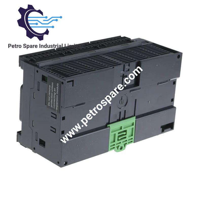
TM221CE40R
Description
Description
Configured for discrete and analog I/O control in the Modicon M221 platform, the Schneider Electric TM221CE40R (TM221CE40R Logic Controller) provides direct PLC execution with 24 discrete inputs, 16 relay outputs, 2 analog inputs, Ethernet, serial communication, USB, and TM3 expansion support.
Hardware Specifications
| Parameter | Specification |
|---|---|
| Model | TM221CE40R |
| Brand | Schneider Electric |
| Product Series | Modicon M221 |
| Product Type | Logic controller |
| Origin | Taiwan (TW) |
| Weight | 0.456 kg |
| Dimensions | 160 mm W x 70 mm D x 90 mm H |
| Mounting | TH35-15 or TH35-7.5 DIN rail; plate or panel |
| Operating Temp | -10 to 55 deg C horizontal; -10 to 35 deg C vertical |
| Storage Temp | -25 to 70 deg C |
| Power Supply | 100 to 240 VAC rated; 85 to 264 VAC limits |
| Power Consumption | 41 VA without I/O expansion; 70 VA with maximum I/O expansion |
| Discrete Inputs | 24, IEC 61131-2 Type 1 |
| Analog Inputs | 2 x 0 to 10 V, 10-bit resolution |
| Relay Outputs | 16 normally open |
| Output Voltage | 5 to 125 VDC; 5 to 250 VAC |
| Output Current | 2 A per output |
| Total I/O | 40 |
| I/O Expansion | Up to 7 local or 14 remote expansion modules |
| Analog Conversion | 1 ms per channel plus one controller cycle |
| Fast Inputs | 4 high-speed inputs, up to 100 kHz, 32-bit HSC |
| Application Memory | 256 kB user application and data RAM |
| Internal Variable RAM | 256 kB |
| Flash Memory | 256 kB |
| Optional Storage | 2 GB SD card |
| Ethernet | 10BASE-T/100BASE-TX, RJ45 |
| Serial Interface | RJ45 RS232/RS485, non-isolated |
| USB | Mini B USB 2.0 |
| Ethernet Services | Modbus TCP client/server, Modbus TCP slave, Ethernet/IP adapter, DHCP client |
| Serial Protocols | Modbus RTU/ASCII, SoMachine-Network |
| Sensor Supply | 24 VDC, 250 mA |
| Protection | IP20 |
| Certifications | CE, UKCA, cULus, DNV-GL, ABS, LR, RCM, EAC |
The controller specifications include the stated 40 I/O configuration, 100 to 240 VAC rated supply, relay outputs, analog inputs, memory, communications, and expansion interfaces.
PLC Backplane and Communication Characteristics
The TM221CE40R supplies 0.52 A on the 5 V expansion bus and 0.24 A on the 24 V expansion bus for connected expansion hardware. The controller supports up to 7 local I/O expansion modules or 14 remote I/O expansion modules.
Ethernet communication uses an RJ45 10BASE-T/100BASE-TX interface with a specified copper cable distance of 100 m. Supported services include Modbus TCP client and server functions and Ethernet/IP adapter operation. The serial RJ45 interface supports RS232 or RS485 communication at up to 115.2 kbit/s.
The relay output stage is rated for 2 A per output, with a maximum current of 7 A per output common. Relay mechanical durability is specified at 20,000,000 cycles, while switching frequency at maximum load is limited to 20 operations per minute.
Frequently Asked Questions
Q: How many expansion modules can the TM221CE40R support?
A: The controller supports up to 7 modules in a local I/O architecture or 14 modules in a remote I/O architecture.
Q: What communication interfaces are integrated?
A: The controller has a Mini B USB 2.0 port, a non-isolated RJ45 RS232/RS485 serial link, and an RJ45 Ethernet interface.
Q: What are the analog input characteristics?
A: There are 2 analog inputs with a 0 to 10 V range and 10-bit resolution. The specified conversion time is 1 ms per channel plus one controller cycle.
Field Installation Guidelines
- Mount the controller on a TH35-15 or TH35-7.5 DIN rail compliant with IEC 60715, or use the specified plate/panel mounting arrangement.
- Maintain the specified installation orientation when applying the operating temperature limits. Horizontal installation permits -10 to 55 deg C; vertical installation permits -10 to 35 deg C.
- Route analog input wiring separately from relay output and high-current conductors where practical. The specified maximum analog cable length is 1 m for unshielded wiring.
- Use shielded cabling for fast-input circuits where the specified cable limit is 10 m. Digital input and relay output wiring have specified maximum distances of 30 m when unshielded.
- Connect removable terminal blocks with power isolated during installation and maintenance. Verify the supply range before energizing the controller.
- Keep Ethernet and serial communication wiring separated from relay output wiring to reduce conducted coupling.
- Ensure the IP20 protective cover is correctly installed after wiring.
- Observe the specified insulation ratings when connecting field circuits. The source specifies 500 VAC insulation between inputs and internal logic and 2300 VAC between the supply and internal logic.
Product Benefits
Product Benefits
- 100% genuine products in stock with fast delivery. Learn more...
- 30-day return policy for quality assurance. Learn more...
- 12-month warranty for peace of mind. Learn more...
Reviews
Reviews