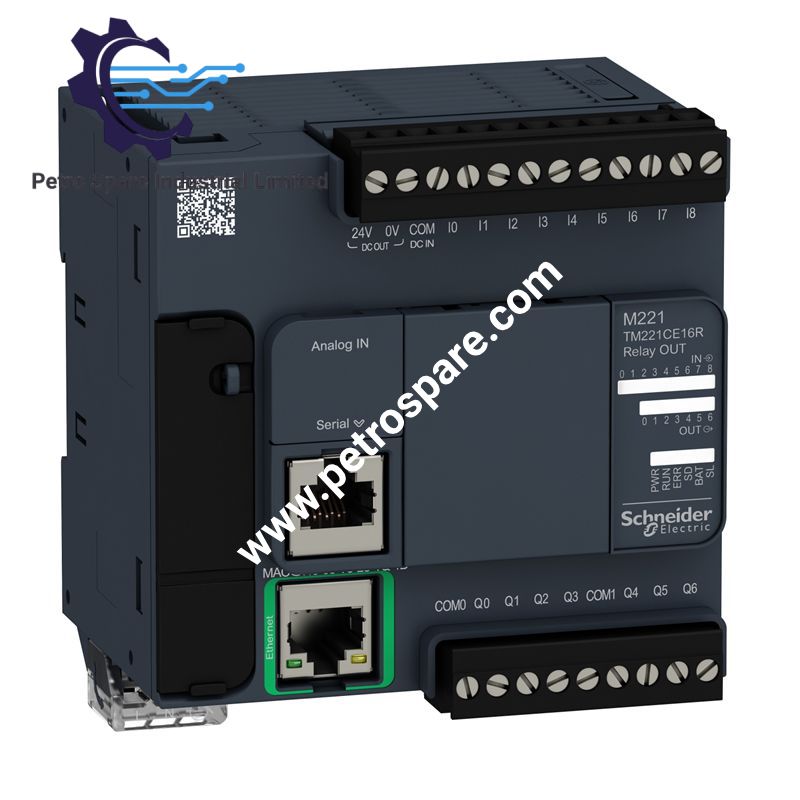
TM221CE16R
Description
Description
Configured for discrete and analog I/O control with Ethernet and serial communications in the Modicon M221 platform, the Schneider Electric TM221CE16R (TM221CE16R Logic Controller) provides direct electrical I/O processing, relay switching, and network communication.
Hardware Specifications
| Parameter | Specification |
|---|---|
| Model | TM221CE16R |
| Brand | Schneider Electric |
| Product Type | Logic Controller |
| Series | Modicon M221 |
| Origin | Taiwan (TW) |
| Weight | 0.346 kg |
| Dimensions | 95 mm W x 70 mm D x 90 mm H |
| Operating Temp | -10 to 55 deg C horizontal; -10 to 35 deg C vertical |
| Power Consumption | 33 VA without I/O expansion; 49 VA with maximum I/O expansion |
| Rated Supply Voltage | 100 to 240 VAC |
| Supply Voltage Limits | 85 to 264 VAC |
| Discrete Inputs | 9, IEC 61131-2 Type 1 |
| Analog Inputs | 2, 0-10 V |
| Discrete Outputs | 7 normally open relay outputs |
| Output Voltage | 5 to 125 VDC; 5 to 250 VAC |
| Output Current | 2 A per output |
| Total I/O | 16 |
| Analog Input Resolution | 10 bit |
| Analog Input Conversion | 1 ms per channel plus one controller cycle |
| Fast Inputs | 4 HSC inputs, up to 100 kHz, 32 bit |
| Expansion Modules | Up to 4 local I/O modules or 11 remote I/O modules |
| Internal Variables RAM | 256 kB |
| Application and Data RAM | 256 kB |
| Built-in Flash | 256 kB |
| Optional Storage | 2 GB SD card |
| Ethernet | 10BASE-T/100BASE-TX, RJ45 |
| Serial Interface | RS232/RS485, RJ45, non-isolated |
| USB Interface | Mini B USB 2.0 |
| Ethernet Protocols | Modbus TCP, Ethernet/IP adapter |
| Serial Protocols | Modbus RTU/ASCII, SoMachine-Network |
| Ethernet Cable Distance | Up to 100 m |
| IP Rating | IP20 |
| Mounting | TH35-15 or TH35-7.5 DIN rail; plate or panel |
| Sensor Supply | 24 VDC, 250 mA |
| Maximum Inrush Current | 40 A |
| Electrical Durability | Up to 300000 relay switching cycles under specified loads |
| Mechanical Durability | 20000000 relay cycles |
| Reset Time | 1 s |
| Insulation | Up to 2300 VAC between specified supply, logic, and output circuits |
| Certifications | CE, cULus, LR, RCM, EAC, ABS, DNV-GL, UKCA, cULus HazLoc |
Modicon M221 I/O and Ethernet Architecture
The TM221CE16R provides 9 discrete inputs, 2 analog 0-10 V inputs, and 7 normally open relay outputs. The discrete inputs support sink or source logic at 24 VDC. Four inputs can operate as high-speed counters at up to 100 kHz with 32-bit counting. The controller supports up to 4 local I/O expansion modules or 11 remote I/O expansion modules.
The Ethernet interface uses an RJ45 connector with 10BASE-T/100BASE-TX operation and supports Modbus TCP server, client and slave functions plus Ethernet/IP adapter operation. The serial RJ45 interface supports RS232/RS485 communication at up to 115.2 kbit/s.
Frequently Asked Questions
Q: What is the relay output electrical range?
A: The relay outputs are rated for 5 to 125 VDC or 5 to 250 VAC, with a specified output current of 2 A.
Q: Can the controller be expanded with additional I/O?
A: Yes. The controller supports up to 4 local I/O expansion modules or 11 remote I/O expansion modules.
Q: What communication interfaces are integrated?
A: The controller has one Mini B USB 2.0 port, one non-isolated RJ45 serial interface supporting RS232/RS485, and one RJ45 Ethernet interface supporting 10BASE-T/100BASE-TX.
Field Installation Guidelines
- Install the controller on a TH35-15 or TH35-7.5 DIN rail according to IEC 60715, or use an appropriate plate or panel fixing arrangement.
- Maintain the specified installation orientation because the allowable operating temperature differs between horizontal and vertical mounting.
- Keep analog input wiring separated from relay output and high-current wiring to reduce electrical interference.
- Use shielded cabling where required by the installation environment, particularly for fast or noise-sensitive signals.
- The specified maximum analog input cable distance is 1 m. Fast input cable distance is limited to 10 m with shielded cable.
- Digital input and relay output cable distances are specified up to 30 m using unshielded cable.
- Connect protective earth and supply wiring according to the applicable installation standard and cabinet grounding scheme.
- Observe the stated insulation boundaries when routing supply, I/O, Ethernet, serial, and sensor circuits.
- Verify the 100 to 240 VAC nominal supply range and the 85 to 264 VAC supply limits before energizing the controller.
- Keep Ethernet and serial communication wiring separated from high-voltage relay circuits where practical.
- Confirm the removable terminal blocks are fully seated and mechanically secured before applying power.
Product Benefits
Product Benefits
- 100% genuine products in stock with fast delivery. Learn more...
- 30-day return policy for quality assurance. Learn more...
- 12-month warranty for peace of mind. Learn more...
Reviews
Reviews