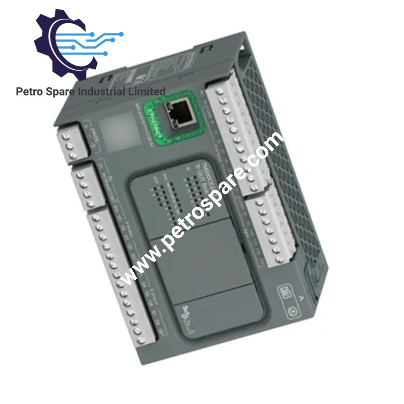
TM200CE24U
Description
Description
Configured for discrete I/O processing, motion pulse generation, and Modbus communication in the Easy Modicon M200 platform, the Schneider Electric TM200CE24U (TM200CE24U Logic Controller) provides 24 VDC control with transistor sink outputs, high-speed inputs, Ethernet Modbus TCP/IP, RS485, and USB connectivity.
Hardware Specifications
| Parameter | Specification |
|---|---|
| Model | TM200CE24U |
| Brand | Schneider Electric |
| Series | Easy Modicon M200 |
| Product Type | Logic Controller |
| Rated Supply Voltage | 24 VDC |
| Supply Voltage Range | 20.4-28.8 VDC |
| Discrete I/O | 24 |
| Discrete Inputs | 14: 4 fast, 4 very fast, 6 normal |
| Discrete Outputs | 10 transistor sink outputs; 2 fast outputs |
| Input Current | 7 mA per input |
| Output Voltage | 24 VDC |
| Output Current | 0.5 A |
| Maximum Common Output Current | 2 A at COM 0; 3 A at COM 1 |
| Fast Output Frequency | 100 kHz, Q0-Q1 in PWM/PLS mode |
| High-Speed Counter Inputs | 4 channels, 100 kHz, 32 bit |
| PID Control | Up to 14 simultaneous loops |
| Serial Communication | RS485, Modbus RTU/ASCII |
| Ethernet | 10/100 Base-T, Modbus TCP/IP |
| USB | Mini-B USB 2.0, 12 Mbit/s |
| Program Backup Memory | 512 byte internal flash |
| Optional Storage | 32 GB Micro-SD card |
| Power Consumption | 10 W at 24 VDC with maximum I/O; maximum consumption 18 W |
| Dimensions | 130 x 70 x 90 mm (W x D x H) |
| Weight | 0.391 kg |
| Operating Temp | 0-55 deg C, horizontal mounting |
| Storage Temp | -25-70 deg C |
| Protection Rating | IP20 with protective cover |
| Mounting | TH35-15 DIN rail or TH35-7.5 panel mounting |
| Input Response Time | 5 us to 100 us depending on input group |
| Output Response Time | 1 ms |
| Output Protection | Overload and short-circuit protection at 3.8 A |
| Maximum Output Leakage Current | 0.1 mA |
| Maximum Voltage Drop | <1 V |
| Isolation | 500 V AC or 500 V DC isolation between specified I/O, supply, and internal logic circuits |
| Maximum Ethernet Cable Distance | 100 m |
| Maximum RS485 Bus Length | 15 m at specified transmission rates |
| Certifications | CE, CSA, IACS E10, RCM, cULus |
| Standards | IEC 61131-2, IEC 61010-2-201 |
Source specifications identify 24 discrete I/O, 24 VDC operation, transistor outputs, 0.5 A output current, and 10 W consumption at maximum I/O. Physical dimensions, weight, mounting, and operating temperature are specified as 130 x 70 x 90 mm, 0.391 kg, DIN rail/panel mounting, and 0-55 deg C respectively.
Industrial Control and I/O Scaling
The TM200CE24U uses 14 discrete inputs and 10 transistor outputs, with Q0-Q1 supporting PWM, PLS, and PTO functions at up to 100 kHz. Four high-speed counter inputs support 100 kHz operation with 32-bit counting. The controller also supports up to four I/O expansion modules, allowing the local I/O configuration to be extended beyond the integrated channels.
For communication, the controller provides Ethernet Modbus TCP/IP through an RJ45 interface, RS485 serial communication for Modbus RTU/ASCII, and Mini-B USB for programming. Ethernet communication is specified at 10/100 Mbit/s, while RS485 supports 1.2-115.2 kbit/s.
Frequently Asked Questions
Q: What type of outputs does the TM200CE24U use?
A: It uses 10 transistor outputs with negative logic, sink configuration. Q0-Q1 are fast outputs supporting PWM, PLS, and PTO functions at up to 100 kHz.
Q: What communication interfaces are integrated?
A: The controller provides Mini-B USB 2.0, RS485 serial communication, and 10/100 Base-T Ethernet with Modbus TCP/IP.
Q: What are the specified environmental operating limits?
A: The operating ambient temperature is 0-55 deg C for horizontal installation. Relative humidity is specified as 10-95% without condensation.
Field Installation Guidelines
- Mount the controller on a TH35-15 DIN rail or TH35-7.5 panel mounting arrangement according to the specified mounting method.
- Connect the 24 VDC supply through the dedicated removable terminal block and maintain the specified 20.4-28.8 VDC supply range.
- Route Ethernet and RS485 communication wiring separately from high-current switching conductors where practical to reduce electrical interference.
- Use shielded wiring for the specified high-speed input cable installations; the source specifies a maximum 10 m cable distance for shielded fast and very-fast inputs.
- Verify input and output group wiring against the specified 500 V isolation boundaries before energizing the controller.
- Keep the protective cover installed where the IP20 protection condition is required.
Product Benefits
Product Benefits
- 100% genuine products in stock with fast delivery. Learn more...
- 30-day return policy for quality assurance. Learn more...
- 12-month warranty for peace of mind. Learn more...
Reviews
Reviews