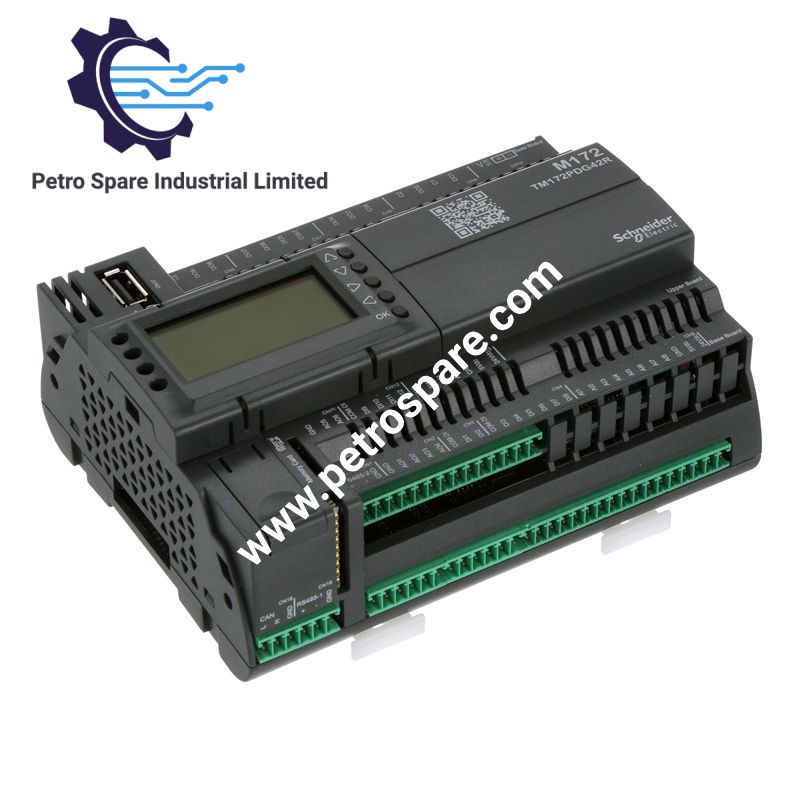
TM172PDG42R
Description
Description
Configured for integrated control, local parameter adjustment, and Ethernet/serial communication in Modicon M171/M172 platforms, the Schneider Electric TM172PDG42R (TM172PDG42R Programmable Controller) provides 42 integrated I/O channels with Modbus, BACnet, WebVisu, USB, CAN, and Ethernet interfaces. The controller operates from 24 VAC/DC and includes a front LCD, keypad, Micro-SD slot, and relay outputs.
Hardware Specifications
| Parameter | Specification |
|---|---|
| Model | TM172PDG42R |
| Brand | Schneider Electric |
| Series | Modicon M171/M172 |
| Product Type | Programmable Controller |
| Application | HVAC and pumping control |
| Total I/O | 42 |
| Digital Inputs | 12, 24 VAC/DC |
| Digital Input Current | 2.5 mA |
| Input Impedance | 10 kOhm |
| Analog Inputs | 12, pairwise configurable |
| Analog Input Signals | 0-10 V, 0-20 mA, 4-20 mA, NTC, PTC, Pt1000, resistance and direct input |
| Analog Input Temperature Range | NTC -50 to 110 deg C; NTC -40 to 150 deg C; PTC -55 to 150 deg C; Pt1000 -200 to 850 deg C |
| Analog Input Resolution | 0.1 deg C for specified temperature inputs |
| Analog Outputs | 6 |
| Analog Output Signals | 0-10 V; 4-20 mA; PWM up to 2 kHz on specified channels |
| Digital Outputs | 12 integrated outputs, relay configuration |
| Relay Output Current | 1 A for SPDT; 3 A for SPST |
| Ethernet | 1 x RJ45, Modbus TCP, BACnet IP, WebVisu, FTP |
| RS485 | 2 interfaces, Modbus serial link or BACnet MS/TP |
| CAN | 1 x CAN port |
| USB | 1 x USB Type A; 1 x USB Mini-B |
| Display | Backlit LCD, 128 x 64 pixels |
| Local Storage | 1 x Micro-SD card slot |
| Controller Supply | 24 VAC +/- 10%; 20-38 VDC |
| Power Consumption | 15 W at 24 VAC/DC |
| Sensor Supply | 5 VDC at 50 mA; 24 VDC at 150 mA |
| Mounting | 35 mm DIN rail or mounting plate |
| Dimensions | 144 mm W x 110 mm H x 60.5 mm D |
| Weight | 0.385 kg |
| Operating Temp | -20 to 60 deg C; -20 to 65 deg C with derating |
| Storage Temp | -30 to 70 deg C |
| Relative Humidity | 5-95%, non-condensing |
| Protection Rating | IP20 |
| Pollution Degree | 2 |
| Operating Altitude | 0-2,000 m |
| Certifications | CE, EAC, CSA, cURus |
| Standards | EN/IEC 60730, UL94 V0 |
| Recommended Replacement | TM172PDG42RI |
| EAN | 3606480894886 |
Ethernet, I/O Density and Control Interfaces
The TM172PDG42R integrates 42 I/O points in a single controller, comprising 12 digital inputs, 12 analog inputs, 12 digital outputs, and 6 analog outputs. The Ethernet interface provides Modbus TCP master/slave and BACnet IP communication together with WebVisu and FTP functions.
Two RS485 interfaces support Modbus serial link or BACnet MS/TP operation. The controller also provides a CAN interface and separate USB Type A and Mini-B interfaces. The USB interfaces support program transfer and PC programming functions.
The analog input architecture accepts voltage, current, resistance, and temperature sensor signals. Selected temperature channels support 0.1 deg C resolution. The digital inputs accept sink or source logic and operate from 24 VAC/DC.
Frequently Asked Questions
Q: What is the nominal power supply for the TM172PDG42R?
A: The controller accepts 24 VAC with a +/- 10% tolerance or 20-38 VDC. The specified power consumption is 15 W at 24 VAC/DC.
Q: How is the controller mounted?
A: The TM172PDG42R can be installed on a 35 mm DIN rail or on a mounting plate using the specified mounting accessories.
Q: Which communication interfaces are integrated?
A: The controller provides one Ethernet RJ45 interface, two RS485 interfaces, one CAN port, one USB Type A port, and one USB Mini-B port. Ethernet supports Modbus TCP and BACnet IP, while the RS485 interfaces support Modbus serial link or BACnet MS/TP.
Field Installation Guidelines
- Verify the supply type before energizing. Use 24 VAC within the specified tolerance or 20-38 VDC.
- Install the controller on a 35 mm DIN rail or mounting plate with adequate mechanical retention.
- Maintain physical separation between low-level analog wiring and high-current relay or power wiring to reduce electrical interference.
- Use twisted and appropriately shielded cable for communication and low-level analog circuits where required by the installation environment.
- Connect cable shields according to the plant grounding scheme and avoid creating unintended shield current paths.
- Check the polarity and signal reference of 24 VDC, 4-20 mA, 0-10 V, RS485, and other field circuits before commissioning.
- Do not exceed the specified relay output current. SPDT outputs are rated at 1 A and specified SPST relay configurations at 3 A.
- Provide adequate ventilation around the controller and account for the stated operating temperature and derating conditions.
- The IP20 enclosure requires installation inside an enclosure or panel providing the required environmental protection.
- For an existing TM172PDG42R installation, verify hardware and application compatibility before migration to the recommended TM172PDG42RI replacement.
Product Benefits
Product Benefits
- 100% genuine products in stock with fast delivery. Learn more...
- 30-day return policy for quality assurance. Learn more...
- 12-month warranty for peace of mind. Learn more...
Reviews
Reviews