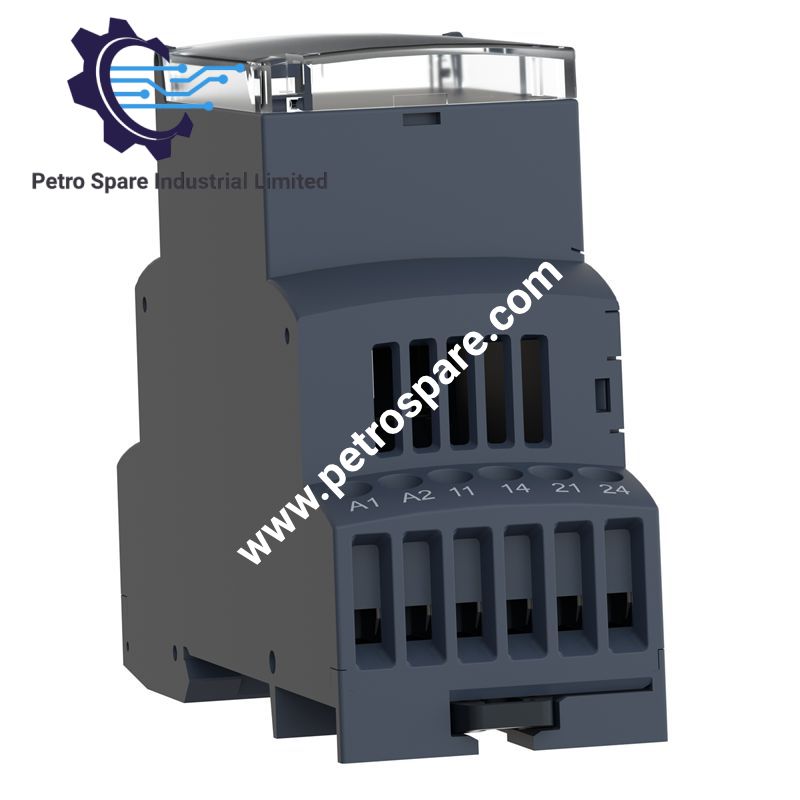
RM35TM50MW
Description
Description
Configured for three-phase motor monitoring and PTC temperature protection, the Schneider Electric RM35TM50MW (RM35TM motor temperature control relay) provides direct electrical monitoring of phase sequence, phase failure, and motor temperature through a PTC sensing circuit. The relay provides two normally open output contacts for hard-wired control logic.
Hardware Specifications
| Parameter | Specification |
|---|---|
| Model | RM35TM50MW |
| Brand | Schneider Electric |
| Product Series | Harmony Control Relays |
| Product Type | Motor temperature control relay |
| Application | 3-phase supply |
| Monitored Parameters | Phase sequence, phase failure, motor temperature via PTC probe |
| Control Circuit Voltage | 24...240 V AC/DC |
| Rated Supply Voltage | 24...240 V AC/DC, 50/60 Hz |
| Supply Voltage Limits | 20.4...264 V AC; 20.4...264 V DC |
| Measurement Range | 208...480 V AC; 15...3100 Ohm |
| Measurement Voltage Limits | 176...528 V AC |
| Output Contacts | 2 NO |
| Nominal Output Current | 5 A |
| Maximum Switching Voltage | 250 V AC |
| Switching Capacity | 1250 VA |
| Maximum Switching Current | 5 A AC; 5 A DC |
| Minimum Switching Current | 10 mA at 5 V DC |
| Electrical Durability | 100000 cycles |
| Mechanical Durability | 30000000 cycles |
| PTC Tripping Threshold | 3100 Ohm +/- 10% |
| PTC Reset Threshold | 1650 Ohm +/- 10% |
| Maximum PTC Sensor Resistance | 1500 Ohm at 20 deg C |
| Reset Time | 10000 ms output |
| Response Time | > 50 ms |
| Power Consumption | 0...4 VA at 24...240 V AC; 0.5 W DC |
| Operating Temperature | -20...50 deg C |
| Storage Temperature | -40...70 deg C |
| Relative Humidity | 95% at 55 deg C |
| Protection Rating | IP20 terminals; IP30 casing |
| Dielectric Test Voltage | 2 kV, 1 min AC 50 Hz |
| Insulation Resistance | > 500 MOhm at 500 V DC |
| Rated Insulation Voltage | 400 V |
| Mounting | 35 mm symmetrical DIN rail, IEC 60715 |
| Dimensions | 35 mm W x 90 mm H x 72 mm D |
| Weight | 0.095 kg |
| Terminals | Screw terminals |
| Tightening Torque | 0.6...1 N.m |
| Housing Material | Polycarbonate |
| Standards | IEC 60255-6; IEC 60034-11-2 |
| Certifications | GL, UL, GOST, C-Tick, CSA |
| Environmental EMC | IEC 61000-6-2, IEC 61000-6-3, IEC 61000-6-4 |
Phase Monitoring and PTC Temperature Control
The RM35TM50MW monitors a 3-phase supply for phase sequence and phase failure while separately evaluating motor temperature through a PTC probe connected to the temperature control circuit. The temperature circuit trips at 3100 Ohm +/- 10% and resets at 1650 Ohm +/- 10%.
The two output contacts are normally open and are rated at 5 A. The relay does not include a test button. Local status indication is provided by LEDs for power, phase relay status, and temperature relay status.
The non-self-powered supply accepts 24...240 V AC/DC. The modular housing mounts on a 35 mm symmetrical DIN rail and provides screw-terminal connections for the supply, monitored circuits, PTC input, and relay outputs.
Frequently Asked Questions
Q: What type of temperature sensor does the RM35TM50MW monitor?
A: It monitors a motor PTC probe through the T1-T2 temperature control circuit. The specified tripping threshold is 3100 Ohm +/- 10%, with a reset threshold of 1650 Ohm +/- 10%.
Q: What are the output contact ratings?
A: The relay provides 2 normally open contacts. The nominal output current is 5 A, with a maximum switching voltage of 250 V AC and a maximum switching current of 5 A AC or 5 A DC.
Q: What mounting arrangement is specified for the relay?
A: The relay is designed for mounting on a 35 mm symmetrical DIN rail conforming to IEC 60715. The housing can operate in any position without derating.
Field Installation Guidelines
- Mount the relay on a 35 mm symmetrical DIN rail with sufficient clearance for terminal wiring and access to the front adjustment elements.
- Verify the three-phase supply connections and phase-monitoring circuit before energizing the relay.
- Route PTC sensor wiring separately from high-current motor conductors where practical to reduce electrical interference.
- Maintain correct polarity and terminal identification for the PTC circuit according to the applicable wiring diagram.
- Connect protective and control wiring according to the installation documentation and the required control circuit architecture.
- Tighten screw terminals within the specified 0.6...1 N.m range.
- Verify that connected relay loads remain within the 5 A output rating and the applicable switching capacity.
- Check the enclosure and terminal protection requirements before installation in environments with conductive contamination or elevated humidity.
- Confirm phase sequence, phase-failure response, and PTC trip/reset operation during commissioning.
- Do not apply a supply voltage outside the specified 20.4...264 V AC/DC range.
Product Benefits
Product Benefits
- 100% genuine products in stock with fast delivery. Learn more...
- 30-day return policy for quality assurance. Learn more...
- 12-month warranty for peace of mind. Learn more...
Reviews
Reviews