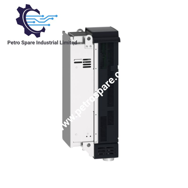
ATV930D45N4
Description
Description
The Schneider Electric ATV930D45N4, also cataloged as the ATV930D45N4 variable speed drive, controls 3-phase synchronous or asynchronous motors from a 380 to 480 VAC supply. It provides 88 A normal-duty output current, 74.5 A heavy-duty output current, an integrated braking chopper, IP21 protection, and EtherNet/IP, Modbus TCP, and Modbus serial interfaces.
Hardware Specifications
| Parameter | Specification |
|---|---|
| Model | ATV930D45N4 |
| Brand | Schneider Electric |
| Series | Altivar Process ATV900 |
| Product Type | Variable Speed Drives |
| Variant | Standard version with braking chopper |
| Motor Type | Synchronous and asynchronous motors |
| Rated Supply Voltage | 380-480 VAC, 3-phase |
| Supply Frequency | 50-60 Hz |
| Motor Power | 45 kW normal duty; 37 kW heavy duty |
| Continuous Output Current | 88 A normal duty; 74.5 A heavy duty |
| Maximum Transient Current | 105.6 A for 60 s normal duty; 111.8 A for 60 s heavy duty |
| Maximum Output Frequency | 599 Hz |
| Nominal Switching Frequency | 4 kHz |
| Adjustable Switching Frequency | 2-16 kHz |
| Brake Chopper | Integrated |
| IP Protection | IP21 |
| Communication | EtherNet/IP, Modbus TCP, Modbus serial |
| Ethernet Rate | 10/100 Mbit/s |
| Modbus Serial Rate | 4.8, 9.6, 19.2, 38.4 kbit/s |
| Physical Interfaces | Ethernet, 2-wire RS 485 |
| Ethernet Connector | 2 x RJ45 |
| Analog Inputs | 3 x configurable 0-10 VDC or 0-20 mA / 4-20 mA, 12 bit |
| Analog Outputs | 2 x configurable 0-10 VDC or 0-20 mA, 10 bit |
| Digital Inputs | 10, including STO inputs |
| Digital Outputs | 2 |
| Relay Outputs | 3 |
| Safe Torque Off | Yes |
| Safe Stop 1 | Yes |
| Safely Limited Speed | Yes |
| Safe Brake Management | Yes |
| 4-Quadrant Operation | Yes |
| Acceleration/Deceleration | 0.01-9999 s, independently adjustable |
| Width | 226 mm |
| Height | 673 mm |
| Depth | 274 mm |
| Weight | 28.7 kg |
| Operating Temp | -15 to 50 deg C without derating; 50 to 60 deg C with derating |
| Relative Humidity | 5-95%, non-condensing |
| Operating Altitude | Up to 1000 m without derating; derating above 1000 m |
| Cooling Air Volume | 240 m3/h |
| Power Dissipation | 121 W natural convection; 943 W forced convection at 380 V, 4 kHz |
| Noise Level | 71.5 dB |
| Certifications | CSA, UL, TÜV |
| Standards | UL 508C, IEC 61800-3, IEC 61800-5-1, IEC 61000-3-12, IEC 61508, IEC 13849-1 |
PLC Network and Drive Interface
The ATV930D45N4 provides Ethernet communication through two RJ45 interfaces. EtherNet/IP and Modbus TCP operate at 10/100 Mbit/s with half-duplex, full-duplex, and autonegotiation modes. Modbus serial communication uses a 2-wire RS 485 physical interface with RTU framing and configurable 8-bit data with odd, even, or no parity.
The drive also supports optional communication modules for PROFINET, PROFIBUS DP V1, DeviceNet, EtherCAT, CANopen, and Ethernet Powerlink. Optional digital and analog I/O expansion modules and encoder interface modules can extend the control interface.
The drive control section provides three analog inputs, two analog outputs, programmable digital inputs, pulse inputs, relay outputs, and Safe Torque Off inputs. Analog inputs accept voltage or current signals, while the analog outputs can provide voltage or current references.
Frequently Asked Questions
Q: What motor power ratings are specified for the ATV930D45N4?
A: The drive is rated for 45 kW under normal-duty operation and 37 kW under heavy-duty operation.
Q: Does the ATV930D45N4 include a braking chopper?
A: Yes. The specified variant includes an integrated braking chopper.
Q: What are the specified operating temperature limits?
A: Operation is specified from -15 to 50 deg C without derating and from 50 to 60 deg C with a derating factor.
Field Installation Guidelines
Mount the drive vertically within the specified +/- 10 degree installation position. Provide the required clearance and airflow around the enclosure so that the cooling system can maintain the specified thermal conditions.
Separate power wiring from low-level control and communication wiring. Route Ethernet and RS 485 cables away from motor and mains conductors where practical. Use appropriate shield termination and grounding practices for the selected communication and EMC installation method.
Connect line, motor, DC bus, control, and protective-earth conductors to the designated terminals. Verify conductor cross-sections against the installation documentation before energization. The specified terminals accept 35-50 mm2 line conductors, 50 mm2 motor conductors, and 35-50 mm2 DC bus conductors.
Before commissioning, verify supply voltage, motor connections, protective earth continuity, STO wiring, communication addressing, and configured motor parameters. Do not apply control signals until the power wiring and safety circuit have been checked.
Product Benefits
Product Benefits
- 100% genuine products in stock with fast delivery. Learn more...
- 30-day return policy for quality assurance. Learn more...
- 12-month warranty for peace of mind. Learn more...
Reviews
Reviews