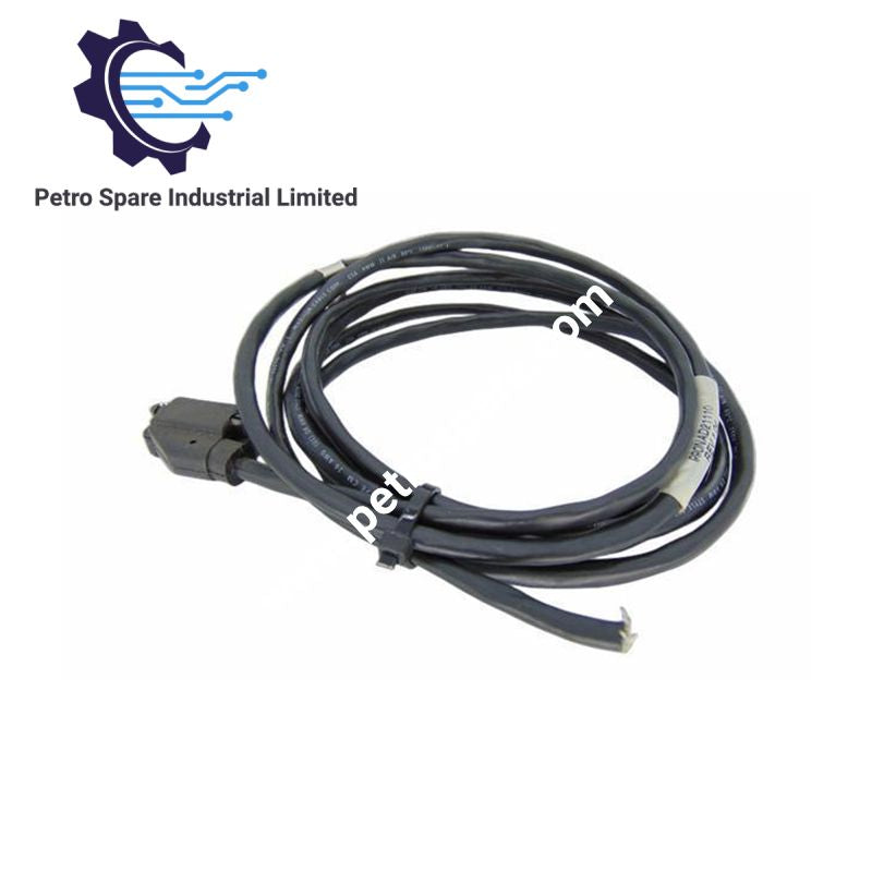
990NAD21110
Description
Description
The Schneider Electric 990NAD21110, also cataloged as the 990NAD21110 Drop Connection Cable, operates as a dedicated hardware component for connecting Momentum I/O sub-bases to local site T-junction taps within Modbus Plus communication networks.
Suffix Breakdown & Model Matrix
- 990NAD: Base prefix designating Modicon networking cable assemblies and passive interconnect hardware.
- 21110: Specific part suffix defining a 2.4 m length Modbus Plus drop cable configured with an elbowed SUB-D 9 male connector on the module side and flying leads on the tap side.
Hardware Specifications
| Parameter | Specification |
|---|---|
| Model | 990NAD21110 |
| Brand | Schneider Electric |
| Cable Length | 2.4 m (7.9 ft) |
| Net Weight | 0.169 kg |
| Dimensions (Package 1) | 2.3 cm x 22.5 cm x 22.0 cm |
| Physical Interface | 1 Male SUB-D 9 elbowed (module side) / Free end (tap side) |
| Platform Compatibility | Modicon Momentum, Modicon Quantum, Advantys STB, Premium |
| Device Compatibility | STBNMP2212, 140CPU43412U, 140CPU31110, 490NRP25300 |
| Network Protocol | Modbus Plus |
Deterministic Industrial Backplane & Bus Communication
The 990NAD21110 cable maintains deterministic token-passing communication across Modbus Plus architecture operating at a physical rate of 1 Mbit/s. Signal paths are shielded against electromagnetic interference (EMI) to prevent packet loss during differential data transfer. The elbowed 9-pin SUB-D connector ensures minimal mechanical strain on host communications interfaces, preserving link stability during continuous deterministic bus operations.
Frequently Asked Questions
Q: What is the purpose of the flying lead termination on the site tap end?
A: The ununterminated free end allows direct wiring into field T-junction terminal blocks or line taps (such as 990NAD23000) without adding intermediate plug resistance.
Q: Can this cable be hot-swapped while the Modbus Plus network is active?
A: Dropping a single node from a Modbus Plus network via its drop cable will not collapse the main trunk, but it disrupts token passing to the specific module. Removing the connector requires temporary node offlining in the PLC system logic.
Field Installation Guidelines
- Maintain a minimum bend radius of 50 mm along the length of the cable to avoid degrading internal twisted-pair impedance and shield continuity.
- Connect the elbowed SUB-D 9 male shell directly to the host communication module interface and secure both thumbscrews to ensure proper earth ground contact through the connector frame.
- Wire the stripped free-end conductors to the designated A/B signal and shield terminals on the local site tap, ensuring the drain wire is tied strictly to the network earth point to avoid ground loops.
- Route the cable away from high-voltage AC power lines and variable frequency drives (VFDs) by at least 200 mm to suppress inductive coupling.
Product Benefits
Product Benefits
- 100% genuine products in stock with fast delivery. Learn more...
- 30-day return policy for quality assurance. Learn more...
- 12-month warranty for peace of mind. Learn more...
Reviews
Reviews