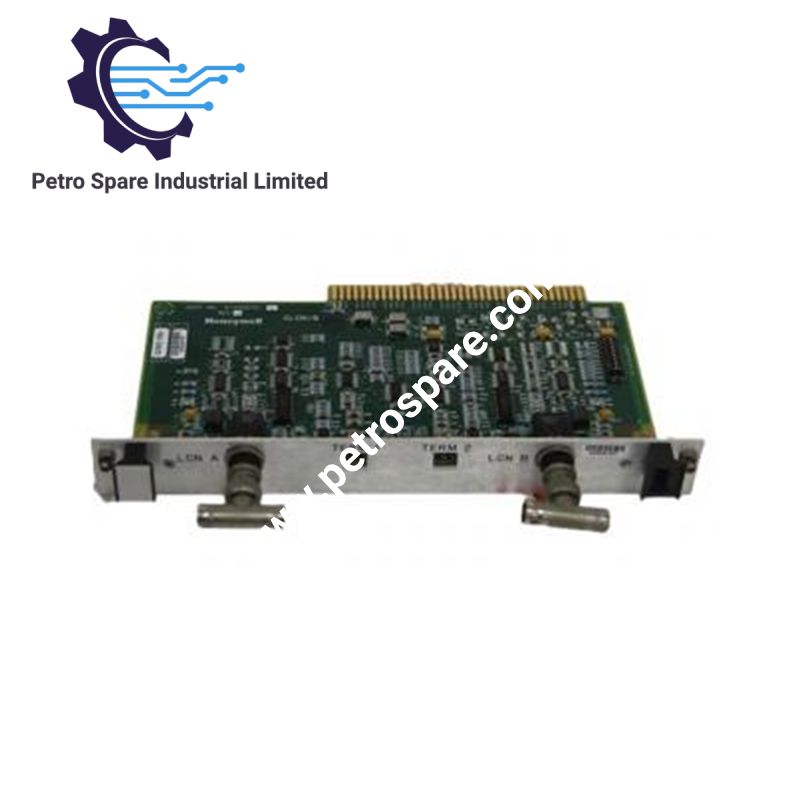


FS-TRO-1024
Description
Description
The Honeywell FS-TRO-1024, also cataloged as the FS-TRO-1024 digital output relay contact field termination assembly (FTA), provides the electrical interface between the SIC-C-12 system interconnection cable and external field wiring. It connects ten output channels from a 10208/2/1 digital output module or redundant module pair to field circuits through screw terminals. The assembly supports standard DIN EN rail mounting and provides relay contact circuit termination.
Hardware Specifications
| Parameter | Specification |
|---|---|
| Model | FS-TRO-1024 |
| Brand | Honeywell |
| Product Type | Digital Output Relay Contact Field Termination Assembly |
| Dimensions | 60 x 70 x 54 mm |
| Number of Channels | 10 |
| Maximum Voltage | 36 VAC / 50 VDC |
| Maximum Switched Power | 100 W / 1000 VA |
| Maximum Continuous Current | 2 A per channel |
| System Interface | SIC-C-12 system interconnection cable |
| Compatible Output Module | 10208/2/1 |
| Field Termination | Screw terminals |
| Maximum Wire Cross-Section | 2.5 mm2 (AWG 14) |
| Wire Stripping Length | 7 mm |
| Terminal Tightening Torque | 0.5 Nm |
| DIN Rail Compatibility | TS32 / TS35 x 7.5 |
| Required Rail Length | 61 mm |
| Overvoltage Category | Category III, according to the supplied IEC 1010 (1990) reference |
| Approvals | CE; UL approval pending in the supplied documentation |
Relay Output Interface and Electrical Limits
The FS-TRO-1024 routes ten digital output channels from the 10208/2/1 module through the SIC-C-12 interconnection cable to field wiring terminals. The connected output module provides the relay contacts; the FTA serves as the field wiring termination interface.
Each channel supports a maximum continuous current of 2 A. The documented maximum switching limits are 36 VAC or 50 VDC and 100 W / 1000 VA. These ratings must be considered together with the connected load characteristics and the output module's contact specifications.
The documentation identifies gold-flush silver-cadmium oxide as the contact material on the 10208/2/1 module. This material specification refers to the output module contacts, not the FS-TRO-1024 terminal assembly itself.
Frequently Asked Questions (FAQ)
Q: Can the FS-TRO-1024 support a redundant pair of 10208/2/1 modules?
A: Yes. The supplied documentation states that the ten channels of a redundant pair of 10208/2/1 modules can be connected to the FTA through the SIC-C-12 cable. The actual redundancy arrangement and switching behavior depend on the system configuration.
Q: What are the electrical limits of the field wiring connections?
A: The documented maximum voltage is 36 VAC or 50 VDC, with a maximum switched power of 100 W / 1000 VA and a maximum continuous current of 2 A per channel. The connected load must remain within the applicable voltage, current, and switching limits.
Q: Which wire sizes and DIN rails are supported?
A: The screw terminals accept conductors up to 2.5 mm2 (AWG 14), with a specified stripping length of 7 mm and tightening torque of 0.5 Nm. Mounting is supported on TS32 and TS35 x 7.5 DIN EN rails, requiring 61 mm of rail length.
Field Installation Guidelines
- DIN rail mounting: Install the FTA on a compatible TS32 or TS35 x 7.5 rail. Allow sufficient clearance for terminal access and cable routing.
- System cable connection: Connect the SIC-C-12 cable according to the applicable system wiring diagram and the manufacturer's SIC-to-FTA application documentation.
- Field wiring: Use conductors with a cross-section no greater than 2.5 mm2. Strip 7 mm of insulation and tighten terminal screws to 0.5 Nm.
- Electrical load verification: Confirm that field circuit voltage, continuous current, and switching power remain within the documented limits. Check AC and DC load characteristics before energizing the circuit.
- Grounding and shielding: Follow the system grounding design and cable shielding requirements. Do not assume that the FTA provides galvanic isolation or a dedicated shield termination without confirmation from the connection documentation.
- Commissioning: Verify terminal assignments, cable continuity, output channel mapping, and field load operation before placing the connected system into service.
Product Benefits
Product Benefits
- 100% genuine products in stock with fast delivery. Learn more...
- 30-day return policy for quality assurance. Learn more...
- 12-month warranty for peace of mind. Learn more...
Reviews
Reviews